Continue to Site

Welcome to EDAboard.com

Welcome to our site! EDAboard.com is an international Electronics Discussion Forum focused on EDA software, circuits, schematics, books, theory, papers, asic, pld, 8051, DSP, Network, RF, Analog Design, PCB, Service Manuals... and a whole lot more! To participate you need to register. Registration is free. Click here to register now.

[SOLVED] making -15/+15v out of single power supply 12Vdc Problem

Status
Not open for further replies.

Freehawk

Full Member level 2
Full Member level 2
Joined
Jan 10, 2016
Messages
122
Helped
0
Reputation
0
Reaction score
0
Trophy points
16
Activity points
1,065
Hello all,
I found this schematic online for making a double supply (+15/-15v) out of a single power supply 12v input

I made the circuit, but it's not giving me the predicted output..

I measure -0.4V and +10.89 volt.

What went wrong ?

I am not an engineer, just hobbyist. I used exactly the same components as in the circuit.
I checked connections, and everything seems to be ok on that matter (no short circuits etc..)

volt-15+15vanaf12v.PNG

Warm regards
 

7815 is a linear regulator, it needs at least 2V dropout voltage, means Vin.min is 15V+2V=17V. It won't work from 12V supply. 7915 has the same issue.
 

Hi,

You could use an inverting buck-boost converter for -15V and a boost converter for +15V from 12V. Might be a challenge for you, I say so because I have no idea of your knowledge and experience, I think these are hard circuits to make work; maybe ready-made ICs are available for both topologies and it's much quicker to go off-the-shelf for this kind of thing anyway.

Have a fun read, chapter 5 and chapter 4 respectively: Power Topologies Handbook Note the schematics shown are simplified topologies...
 

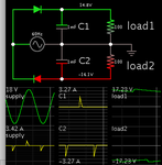
Your schematic is designed to work with an AC supply. For instance a transformer which outputs 12.6V nominal AC. Its waveform has peaks +18 -18.

Simulation showing the concept:

12VAC supply to split bipolar two diodes two caps pos neg loads.png
 

You better to use dual output converter DC DC 15V.png
 

Hi,

You could use an inverting buck-boost converter for -15V and a boost converter for +15V from 12V. Might be a challenge for you, I say so because I have no idea of your knowledge and experience, I think these are hard circuits to make work; maybe ready-made ICs are available for both topologies and it's much quicker to go off-the-shelf for this kind of thing anyway.

Have a fun read, chapter 5 and chapter 4 respectively: Power Topologies Handbook Note the schematics shown are simplified topologies...

Hi,


Maybe i better explain what i am trying to do.
I want to make an op-amp preamp circuit witch needs +15/-15v (also +10/-10 would be ok)
now i made a preamp circuit with a 12v dc input and biased the op-amp, it works (vc/2 on gnd)

I want to try to make next version with +/- dc on the op -amp (dont know if i am expressing myself correctly, but hopefully you understand what i mean :))

So i searched for schematics of pre-amps (professional ones) that uses 12vdc and found this schema -)
An i tought it could be do-able

But if you can lead me to a better solution (a pre made something), mayb i just have to buy an 15v AC power supply :)

Warm regards
 

Hi,

Preamp: ... can be anything from DC to RF, no idea what circuit you use.

OPAMP power supply:
Usually not that critical, because OPAMPs usually have a wide operating power supply area and good PSRR. For details check datasheet.

Wheter power supply voltage fluctuation influences the output mainly depends on the circuit (not the OPAMP itself).

You say "making -15/+15v out of single power supply 12Vdc"
But as Brad already mentioned your power supply circuit is designed for 12V AC input.

Now you have a lot of options:
* use 12V AC input with your circuit
* buy a +/-12V supply
* use a 12V --> +/-15V DCDC converter
* use single supply and combine it with a voltage inverter (like ICL7660)
* and several other solutions

It depends on cost, effort, size, electrical requirements... All this we don´t know, thus it´s impossble to give good assistance.


Klaus
 

also +10/-10 would be ok)

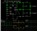
A half-bridge (as found in the output stage of a 555 IC) can drive a two-capacitor stack to create a split supply. In this manner you can start with a single 12VDC supply, and get +11 -11VDC.

555 drives 12VDC  2 diodes 2 caps 2 loads split supply 11V each.png

The two smoothing capacitors create a new split supply for the op amp. Do not connect the op amp to the same ground where you have the 555 grounded.

The two loads represent various current flows in the op amp, as its output wire assumes various positive or negative volt levels.
 

It's a simple audio preamp

Just amplifying audio signals
 

Hi,

It's a simple audio preamp
but too secret to show us?

The better your information, the better our help.

Klaus
 

Hi,


but too secret to show us?

The better your information, the better our help.

Klaus


Its not secret :) but it's now in a single supply version with inverting op-amps circuit.

I wanted to try to generate a dual supply just for reasons of learning and maybe have a more stable circuit (now i have to bias the opamp)

But guess what, i mad my circuit more or less work
the layout of pins of the LM7915c regulator is different than pinlayout of the LM340T15-7815.

The ground pin is the first one , and not the middle one

I must confess i also use an AC/AC adapter of 9v

But now i am measuring +15.02v / -14.50v

I don't know how important it is that its really +15/-15 and if it is how to solve it.
But anyway, it's more like it then before i guess

- - - Updated - - -

Its not secret :) but it's now in a single supply version with inverting op-amps circuit.

I wanted to try to generate a dual supply just for reasons of learning and maybe have a more stable circuit (now i have to bias the opamp)

But guess what, i mad my circuit more or less work
the layout of pins of the LM7915c regulator is different than pinlayout of the LM340T15-7815.

The ground pin is the first one , and not the middle one

I must confess i also use an AC/AC adapter of 9v

But now i am measuring +15.02v / -14.50v

I don't know how important it is that its really +15/-15 and if it is how to solve it.
But anyway, it's more like it then before i guess


---------------------

I am now measuring +15.08/-15.06 after a minute or 2.

Is it something with the caps???
It takes a while to stabilize

I used polarized caps of .1 uF instead of non polarized, the only thing i did not do according to schematic, is it something to change?
 

The simple circuit needs an input of 12VAC or more and will not produce +15V and -15V with only 9VAC.

I used a 9v AC adapter 11,7VA

And i really measure +15.02 volts between gnd and + side of the circuit

And -14.5 to -15.2 volts between gnd and - side of the circuit.

But it's going down and up very slowly (the neg side) variying between those voltages , strange

But i have for the moment no 12vAC adapter, thats why i tried with 9VAC
 

Hi,

I'm lost here... We're defying hard laws of nature and physics: 9VAC * 1.414 = 12.76VAC. +-15V...? Wow. Somehow your adapter and/or circuit is apparently producing free energy - let's reverse engineer it and get rich! I'd check the DMM against a new 1.5V battey in DC, then measure the +-15VAC. I don't disbelieve you, but find it strange, it must be a very coarse adapter with a wide output tolerance range.

If you actually need anything from this thread, you'll presumably stop wasting members' time by instead of making unsubstantiated claims, posting the schematic of your actual circuit and a short video of the measurements with your DMM, otherwise I'm afraid this is like the tale of the man who went around claiming he could jump ten metres in the air - but only in a far off country and couldn't do so there in front of the people he was telling he could :).


Wow, i didn't mean to waste your time, i did really ask a question..
I posted the circuit in the thread at the start.. I followed it completely with execption of 0.1uF polarized (neg pole to gnd) in stead of non polarized like in the schematics.

I just want to try with an AC12V powersupply but i don't have one for the moment.. and not so common (i didn't find one till now).
Well i might make a video of my measurements but probably you will say then i tricked it :)
But i understand your concerns and will not ask from you anything.
 

Hi,

Some examples.
Look at a picture of a car .... and try to find out if it fits into the garage.
It will be hard to find out without a meaningful photo of the garage.

Similar is with your schematic. You posted a schematic of the power supply ... but your main idea is to build a preamp...without showing us the preamp. You say the preamp will work with +/-15V ... and you expect it to work with +/-10V. Nobody can verify this.

The schematic did not show your wrong connection. An additional photo of your wiring could have shown this.
The schematic shows "how you expect it to be", but the photo shows the reality.

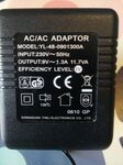
You say the ACAC adapter is 9V. We don't know if this the value printed on the power supply or did you measure the 9V.

Many people act like you do - there is nothing unusual. This is because you have knowledge about your circuit that we don't have...and you have your expectations.

--> To be able to give good assistance we ask for most "objective" and unambigous informations.

Klaus
 

Hi,

Well the 9vAC is on the label of the powersupply, i didn't really think this could be wrong.

But indeed i measure 12.26V AC with my multimeter, so that's why it could make sense now. (shamed now)


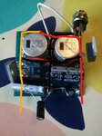
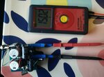
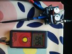
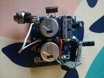
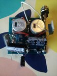
I included pictures of my circuit board, my power supply ..

On the picture of the circuit board you can't see the two diodes but they are there like on the schematic

I also included two picture of my measurements with my multimeter. (now it went to +15.02/ -15.45)

Ok hope that cleares thing out, it was never my intention to annoy people or let them lose their time

Sorry if that was your impression.

Concerning the pre-amplifier. I did only make it in a single supply version (with biased op amps).
I did chose inverting op amp ciruits and i want to do it now with non-inverting, but i tought it could be easier with double supply.
So in fact it's something i will rebuild later on, first i had to try to fix a double supply.
Op amps I will use are OPA1644x

But anyway, is this more like it?
What i noticed also that when i put leds on the circuit
Then the voltage on de - side changes to -9 V DC and on the + side 14.8V DC (led + resistor 400ohm)

I think there is still a fault in my circuit but i don't know what exaclty

circuit-edited.jpgcircuit5.jpgcircuit4.jpgcircuit3.jpgcircuit2.jpgcircuit.jpg


Hi,

Some examples.
Look at a picture of a car .... and try to find out if it fits into the garage.
It will be hard to find out without a meaningful photo of the garage.

Similar is with your schematic. You posted a schematic of the power supply ... but your main idea is to build a preamp...without showing us the preamp. You say the preamp will work with +/-15V ... and you expect it to work with +/-10V. Nobody can verify this.

The schematic did not show your wrong connection. An additional photo of your wiring could have shown this.
The schematic shows "how you expect it to be", but the photo shows the reality.

You say the ACAC adapter is 9V. We don't know if this the value printed on the power supply or did you measure the 9V.

Many people act like you do - there is nothing unusual. This is because you have knowledge about your circuit that we don't have...and you have your expectations.

--> To be able to give good assistance we ask for most "objective" and unambigous informations.

Klaus
 

Hi,

Things clearing up...

AC supply 9V:
For a short circuit proof AC adapter it is not unusual, that the "no load" output voltage is that high.
But expect less output voltage when loaded. Like 9V at an ohmic load that draws 1.3A.
But your bridge rectified supply circuit is no ohmic load. This makes voltage calculation a bitw difficult.

Voltage regulators:
You urgently need to read the datasheets.
They tell (TI LM79xx datasheet) you that the ouput voltage of an LM7915 may be -14.4V ... -15.6V at 0.5A load and -14.25V ... -15.75V with 5mA ... 1A load.
I assume you measure without load. Not even with the 5mA of the datasheet condition. Thus you can expect even wider variation.

Additionally it tells you you need at least -17.5V input voltage. Don´t go below that - not even for worst case conditions: Full load, lowest expectable line voltage,.. not even for a millisecond.

I´m not sure you can guarantee this. (fluctuating ouptut voltage lets me assume you are too close to the limit) Thus I recommend to use +12V and -12V regulators. They need at least 14.5V. This should be OK.
...and the preamp will be happy with +/-12V.
Maybe it´s a good idea to run a LED with 5mA at each ouput. It gives some optical feedback and ensures a minimum load.

So i searched for schematics of pre-amps (professional ones) that uses 12vdc and found this schema -)
This sounds as if you have a preamp schematic. Where is it?
Best if you could show us your preamp schematic with dual power supply. Hand made is OK.

What i noticed also that when i put leds on the circuit
Then the voltage on de - side changes to -9 V DC and on the + side 14.8V DC (led + resistor 400ohm)
I´m worried about the "-9V" this makes no sense. At this -9V condition, what is the voltage at the regulator input?
400 Ohms. This will cause more than 30mA for a usual LED .. this is too much for usual LEDs.

Klaus
 

Maybe i have to tell how i came to the idea of making this circuit.

I have a presonus audio pre-amp and i compared my pre-amp circuit with it (soundwise)
I noticed on high volume dc ripple in the ac signal (sound) in my circuit but not at all in the presonus pre amp at same volume level.

I tried to find the schematics for that presonus pre-amp to maybe learn how they do it and i saw that they did use a dual-powersupply.
Altough this presonus pre-amp comes with an external 12v DC power supply. (see atachment of backside presonus 12vDC input)
Therefore i assumed that the circuit i found converted 12vDC to +12v/-12v.

And i tought, yes that's what i want. Because i then don't have to bias the op-amps anymore, and maybe that is the cause of the ripple noise.
I allready used decouple caps on the op-amp. The circuit works and can only hear this ripple noise with cranked up volume, but on the same volume level with the presonus i don't hear this ripple.

The presonus circuit looked very simple :) and i ordered exactly the same components as on the schematics. (that's where the 15v/-15v voltage regulators come from) For me +10/-10 or even +5/-5 is ok. But i don't know if it would work in that circuit (with other voltage regulators of 5 or 10v)
I build it, and then had not the result I expected.
And i don't really understand this circuit, i just copied it so i tought i will ask on a forum, maybe they see immed what is wrong.

And you did help a lot, I now know the circuit needs AC in stead of DC and it needs at least 17V AC.
Still i don't understand how they do that in the presonus pre-amp, there has to be a stage before to convert 12VDC to >=17VAC that isn't documented??? (and is that possible at all?)

So you ask for my pre-amp schematics again :).. But i don't have it right now, i will make it once i have this dual power supply +12/-12v
but also +5v/-5v should do the trick. As long a I don't solve that i cant make my new op-amp circuit. Does sound logical, no? :)


So that was it :)

I don't mean to offend or harass anyone, nor to be recognised as a genius who can make +15/-15v out of a 9vAC supply :)
(I wich it were true hahaha)

I know and understand that's not possible, didn't really claim that, just that i measured these voltages (not knowing that the AC supply really gave 12VAC in stead of 9vAC wich was on the label)


presonus-tube.PNG


Hi,

Things clearing up...

AC supply 9V:
For a short circuit proof AC adapter it is not unusual, that the "no load" output voltage is that high.
But expect less output voltage when loaded. Like 9V at an ohmic load that draws 1.3A.
But your bridge rectified supply circuit is no ohmic load. This makes voltage calculation a bitw difficult.

Voltage regulators:
You urgently need to read the datasheets.
They tell (TI LM79xx datasheet) you that the ouput voltage of an LM7915 may be -14.4V ... -15.6V at 0.5A load and -14.25V ... -15.75V with 5mA ... 1A load.
I assume you measure without load. Not even with the 5mA of the datasheet condition. Thus you can expect even wider variation.

Additionally it tells you you need at least -17.5V input voltage. Don´t go below that - not even for worst case conditions: Full load, lowest expectable line voltage,.. not even for a millisecond.

I´m not sure you can guarantee this. (fluctuating ouptut voltage lets me assume you are too close to the limit) Thus I recommend to use +12V and -12V regulators. They need at least 14.5V. This should be OK.
...and the preamp will be happy with +/-12V.
Maybe it´s a good idea to run a LED with 5mA at each ouput. It gives some optical feedback and ensures a minimum load.


This sounds as if you have a preamp schematic. Where is it?
Best if you could show us your preamp schematic with dual power supply. Hand made is OK.


I´m worried about the "-9V" this makes no sense. At this -9V condition, what is the voltage at the regulator input?
400 Ohms. This will cause more than 30mA for a usual LED .. this is too much for usual LEDs.

Klaus
 

Hi,

I tried to find the schematics for that presonus pre-amp to maybe learn how they do it and i saw that they did use a dual-powersupply.
It´s not the schematic alone that makes good sound. Part selection, PCB layout, wiring, coupling to mains (earth), GND loops .. may also influence AC hum

I now know the circuit needs AC in stead of DC and it needs at least 17V AC
No.
17V at the input at the voltage regulators does not mean the AC is 17V.
When one talks about AC voltage one usually means AC sine RMS.
The diode capacitor solution charges the capacitor to almost the peak value of the sine.
But the peak value of a sine is 1.414 x the RMS value of the sine.

12V AC RMS sine --> 17V peak sine. (positive as well as negative)
Subtract 1 V for the diode drop and another 0.5V for the capacitor voltage ripple then you may expect about 15.5V (with some load current)
(The exact value depends on a lot of things: Mains voltage, transformer, diode, capacitor value, load current, mains frequency....)

Does sound logical, no?
Maybe.
We professionals should do it the other way round.
* decide specifications for the preamp
* desgin preamp circuit
* decide specifications for the supply circuit
* design the supply circuit.

Klaus
 

Status
Not open for further replies.

Similar threads

Part and Inventory Search

Welcome to EDABoard.com

Sponsor

Back
Top