Continue to Site

Welcome to EDAboard.com

Welcome to our site! EDAboard.com is an international Electronics Discussion Forum focused on EDA software, circuits, schematics, books, theory, papers, asic, pld, 8051, DSP, Network, RF, Analog Design, PCB, Service Manuals... and a whole lot more! To participate you need to register. Registration is free. Click here to register now.

DC Input Diode current?

Status
Not open for further replies.

mheruian

Junior Member level 3
Joined
Jan 18, 2018
Messages
31
Helped
0
Reputation
0
Reaction score
0
Trophy points
6
Activity points
412
question1.PNG question2.PNG

Good day,

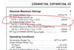
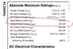
What should I be concern with this? Does this mean that i should always put a series resistor on the input/output pins to control current and avoid ruining the IC? Like if I have dmx having 4 input pins for combinations, i should put 330 ohm resistor in series to each input pins of the dmx to result around 15mA current going in the input pins? (5v / 330 ohm = 0.01515 A; from arduino digital output pin 5V to the dmx input pins)??
 

Re: DC Input Diode Durrent?

These are latchup prevention limits. The right answer is zero
current, which would happen if you stay within the supply
rails. Then you need no resistors.
 
Re: DC Input Diode Durrent?

Hi,

dick_freebird is correct.

Absolute maximum ratings:
Did you notice that the input signal is more than 0.5V beyond the supply rails?
Thi is not the usal operation condition. You should consider this on error case, maybe on input overvoltage, like ESD.
Here a series resistor may be useful to limit the input current.

In the DC characteristics you will find the typical input current when the input signal is within the supply rails.
Usually it's less than 1uA.

Klaus
 
Re: DC Input Diode Durrent?

These are latchup prevention limits. The right answer is zero
current, which would happen if you stay within the supply
rails. Then you need no resistors.

Hi,

dick_freebird is correct.

Absolute maximum ratings:
Did you notice that the input signal is more than 0.5V beyond the supply rails?
Thi is not the usal operation condition. You should consider this on error case, maybe on input overvoltage, like ESD.
Here a series resistor may be useful to limit the input current.

In the DC characteristics you will find the typical input current when the input signal is within the supply rails.
Usually it's less than 1uA.

Klaus

Thanks for the reply, i haven't search any answers on google because whenever i search dc input current diode, different topics are being shown about diode only or dc input only..

Ok, though it's fine to put resistors as long as its w/in the supply voltage range but that makes the resistors useless anyways, did I get that right?

What is the answer on this instance where I'll just use resistors when I input more than the supply range and make sure that the current going there is less than or equal to 1uA or 20mA, like:

Vsupply = 5v
Vinput = 6v

resistor to use is 6M ohm to get 1uA input or it should just be 330 ohm to get 20mA, which one?
 

Hi,

Did you read the datasheet? What value does it say?

to get xx uA input
You don´t need to control this current. It is already limited by the IC`s input circuitry. (@ the given conditions)

Klaus
 

Hi,


Did you read the datasheet? What value does it say?


You don´t need to control this current. It is already limited by the IC`s input circuitry. (@ the given conditions)

Klaus

Hi Mr. Klaus,

I did read it. Sorry for being slow but there's a lot of times I can't read between the lines :sad:

"You don´t need to control this current. It is already limited by the IC`s input circuitry. (@ the given conditions)" ~ this will be the condition (as written on datasheet) only when it is supplied by same voltage input equivalent to Vcc right? so if dmx is supplied by 5v power and you input voltage on its data input pins by 4.2 to 5.0 (same as voltage power supply), the current would only be 1uA.. what happens if you input voltage on its data pins by 6.0 v (greater than dmx's voltage power supply? would the +/-20mA as on absolute ratings be applied on data input pins where this is the time you use resistors??

Thank you so much for all the repLy and heLp. Thanks for having patience to at Least heLp me be enLightened..
 

Hi,

it is supplied by same voltage input equivalent to Vcc right?
each vendor (datasheet) may have other conditions.

--> Thus you need to show us the related datasheet.

Klaus
 
what happens if you input voltage on its data pins by 6.0 v (greater than dmx's voltage power supply? would the +/-20mA as on absolute ratings be applied on data input pins where this is the time you use resistors??

Yes, if the input voltage can be higher than the supply voltage, you should use a series resistor to limit the current. There is no reason to limit the current to exactly 20 mA. If your circuit allows for it, use a higher value resistor to limit the current to a lower value, maybe 5 mA or less (just an example).
 
Hi,

each vendor (datasheet) may have other conditions.

--> Thus you need to show us the related datasheet.

Klaus

Hi Mr. Klaus, thank you so much again, I was referring mostly on the CD74HC154 dmx as this was mostly our sample being discussed instead the other one.

Yes, if the input voltage can be higher than the supply voltage, you should use a series resistor to limit the current. There is no reason to limit the current to exactly 20 mA. If your circuit allows for it, use a higher value resistor to limit the current to a lower value, maybe 5 mA or less (just an example).

Hi Mr. std :D thank you so much! so my guess was right now since you had given a straight forward answer.

I had this thinking where I know it sounds stupid but - if my dmx is powered by 5v and i put resistors like 500 ohm on each input lines of it, that'll result to 1uA current input on these lines regardless the presence of these resistors (right?) but in such cases (if there would be, but I know it's too much low of a chance unless it will be intended) that a 6v was input on the dmx input lines, i have to put series resistors to these since the input current wouldn't be 1uA now. It'll be but more of a milliAmp if I didn't put resistors and would ruin the device if it is over the intended maximum absolute current of 20mA..

(pLease correct me If my conclusions are wrong because, i'm used to interfacing these chips as it is - w/o actually giving a thought on OVERALL specs wherein it puts me on the thought that why other same ICs stiLL have series resistors on their input lines wherein in my experience, w/o these, everything will be fine - because I always follow the minimum requirements of datasheet but doesn't expect the worst where absolute maximum ratings are referring to.. I at least want to understand what are all the specs in the datasheet instead of just complying on the main/basics specs i know of: voltage supply only hehe :lol:)
 

The core question is, will the source voltage ever exceed /
mismatch the destination power rails? I see this being a
concern, but don't see it stated as a likelihood or even a
valid possibility.

Now, two distinct 5V supplies with tolerances -could- put
a volt across an input protection diode under the right,
wrong circumstances (like, source at +10% (5.5V) and
destination at -10% (4.5V)). What can be said about
the uC and the demux's supplies? If they are common
and PCB-local then none of this applies. If you had 5%
tolerance supplies and no great ground loop or supply
loop currents and resistances, you would not see more
than 500mV skew even with separate 5V sources.

"Abnormal conditions" work of this sort always needs a
threat envelope declared, that is sane and complete.
If you just speculate randomly you can't get closure,
let alone confidence in it.
 

Status
Not open for further replies.

Part and Inventory Search

Welcome to EDABoard.com

Sponsor

Back
Top