Continue to Site

Welcome to EDAboard.com

Welcome to our site! EDAboard.com is an international Electronics Discussion Forum focused on EDA software, circuits, schematics, books, theory, papers, asic, pld, 8051, DSP, Network, RF, Analog Design, PCB, Service Manuals... and a whole lot more! To participate you need to register. Registration is free. Click here to register now.

Current transformer - Magnetizing current

Status
Not open for further replies.

david.cano90

Junior Member level 3
Joined
Jul 23, 2018
Messages
26
Helped
1
Reputation
2
Reaction score
1
Trophy points
3
Activity points
243
Hello everyone,

I am designing a current transformer (CT) to sense the current that is flowing in every single switch for a DC-DC converter.
The converter is going to be built through a push-pull topology, and it has to deliver 200 W @200V. The input voltage is 24 V.
The MOSFETs that I chose can deal up to 50 A.
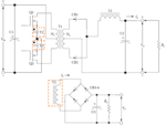
TransCurr.png
(Image taken from: McLyman, C. W. T. (2011). Transformer and Inductor Design Handbook, Fourth Edition. CRC Press.)

Following Mclyman's procedure, I got this:
The peak current that I want to measure for making the Current Mode Control (CMC) is 45 A.
The primary has 1 turn and the the secondary 150. In the secondary I would have 0.3 A. The load of the CT is 2.5 Ohm.
The voltage that I am willing to have when the peak current arises is 0.75 at the secondary of the CT (for the CMC).

I am afraid of the magnetizing current and the losses of the CT.

What do you think about the design? Could the CT work for measuring that amount of current?
If there are troubles, could you please give me a hint or something?

As always, thank you for reading.

I would appreciate your help.

Have a nice day!

David.
 

Hi,

Could the CT work for measuring that amount of current?
I'm confused. Do you want us to check if the CT is suitable?
Without any specification / part number/ datasheet of the CT?
Without knowing about SMPS specifications? Frequency, currents, duty cycle,

Klaus
 

Hello Klaus, Thanks for your reply.

Of course not, sorry about it, my mistake. The material of the ring core (R 34.0 × 20.5 × 12.5, AL=2790 nH) is the N87 by EPCOS TDK (Bsat≈80mT@100kHz).
The SMPS specifications are: 500W, Vi=24V±10%, Vo=200V, Io=2.5A, Dmax=0.77 @Vi_min (each switch would work half of that value tops), and Fsw=100kHz.

I hope this can help you.

David.
 

dB/dt = V / N. Ae 1st you have to decide what sec current you want for 50A in the 1T pri, lets say 50mA, thus the turns ratio is 50/0.05 = 1000:1

thus you need 1000T for the LV sec - you may find this tricky to wind yourself - hence why a lot of people buy ready made ones...

However, you say you want 0.3A on the sec so the sec turns are now 1:166.666... for 1:150 the current would be 0.333A, lets go there.

The LV wire must be sized such that the R is not too large causing volt drop at 333mA.

You have arbitrarily decided the CT load is to be 2.5 ohm, giving 833mV for 333mA ( 0.3 watts diss BTW), lets be clever and use 40V 1A schottkies for the rectifying of the CT current, thus we have to add 2 x 0.45V fwd drop of the schottkies - giving a total Vout of the CT of 0.9 + .833 = 1.733V

plus any IR drop in the wire of the sec - lets say .2 ohm x 0.333A = 66mV giving 1.8V total

from the formula at the start of the above we get: dB = V dt / N. Ae = 1.8 5uS / 150 84E-6 = 0.7mT, Bpk = 0.35mT

So - no problem with saturation. p.s. a low Bpk gives very good accuracy.

The mean length of turn for the sec is ~ 42.5mm giving 6.38m of wire, r = rho L/A where Rho = 17E-9 for copper thus A = 5.42E-9 thus diameter = 0.8mm for 0.2 ohm. This may be a tricky fit, better to use say 0.5mm dia raising the R wdg to 0.55 ohm.

The inner circumference is 64mm, divided by 0.55mm = 116 turns, so 150 turns will fit OK in just over a layer ...

good luck ...

- - - Updated - - -

BTW any cap across the R on the CT output should be small...
 
Also, here is some good knowledge on CSTs...attached
they include LTspice simulations...annotated to give the knowledge to you

- - - Updated - - -

The current appears to be unidirectional in the branches where you have chosen to monitor current…........is there a need for two of them there……..?...wouldnt you just bring the output of each fet to the one current sense transformer. …or put the CST elsewhere. With CST’s you have to watch out for saturation due to magnetizing current as Easy Peasy said…also, you have to watch that your secondary magnetizing inductance isn’t so low that you end up distorting your current waveform with magnetizing current……because as you know, your secondary current in the ideal world would be IS = (NP/NS) * IP……BUT in reality it is not this…because of the contribution of the magnetizing current…this is also why you generally want to keep your secondary voltage down to a minimum…but not so low that you suffer noise issues…..because if you r secondary voltage is too high, then you will get too much magnetixing current in the secondary….in the worst case you could end up with your nice current ramp going down instead of up!
Also, remember that the CST needs to be rest like any switching transformer….so remember to ensure that your volt.seconds_OFF at least equals your volt.seconds_ON
 

Attachments

  • Current sense transformers.zip
    8.6 MB · Views: 137
The OP is ensuring reset ( and lowest B swing) by fitting the CT in the way shown in the pic, you could put a CT in the pos line only, but at 98% on time there is precious little time to reset the CT, and would require a very low capacitance wind and high reset volts on the CT sec.

If you put a 1uF cap across the CT pri then the effect of the gate drive current pulse can be mitigated in the CT output ...
 
Also, here is some good knowledge on CSTs...attached
they include LTspice simulations...annotated to give the knowledge to you

Thanks Treez. That helped a lot.

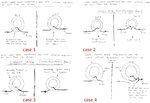
Theres a folder that has interesting images about the leakage inductance caused by the way one build the CT.
I attached them in a single image and I gave them a "name".

I would like to confirm the answers that I have (the question is: what image has less leakage inductance):
Case 1: second
Case 2: first
Case 3: second
Case 4: I don't know. Actually I do find necessary that "hug".

Once again, thank you guys!

cases.jpg
 

yes i reckon they are all fairly poorly coupled, but with CSTs, it doesnt seem to matter too much....once i took apart a CST in a perfectly workign HV buck, and primary and secondary were on different sections of a split bobbin...so relatively poorly coupled....but then again, with a turns ratio of 1:100 or so..how do you ensure really tight pri/sec coupling.
One time a guy told me a CST secondary is like a current source, so leakage inductance doesnt matter so much.
 

For the least leakage inductance ( best coupling ) you need a toroid that is longer (front to back) , with a small inside diameter ( but large enough ID to get the required turns on and still let the pri conductor thru) and an OD that is as small as you can manage ( but not ridiculously thin walled ).

Having said that - if the pri conductor is in the middle of the toroid and the sec is evenly wound - then the leakage is already low by dint of the geometry, and by the high Ur of the core ( steers most of the flux into itself ).

Having thick insulation on the toroid, or additional insulation by way of plastic "cups" or a layer of tape, helps reduce the capacitance to the core of the multi-turn sec winding and this improves the BW of the CT.
 

@David...i am surprised you say "case 2" is the first one.....i think the second one is better coupled as there are more primary turns around the core, and hence very slightly better coupling....more "Involvement" of the pri withh the sec.
 

Status
Not open for further replies.

Similar threads

Part and Inventory Search

Welcome to EDABoard.com

Sponsor

Back
Top