Continue to Site

Welcome to EDAboard.com

Welcome to our site! EDAboard.com is an international Electronics Discussion Forum focused on EDA software, circuits, schematics, books, theory, papers, asic, pld, 8051, DSP, Network, RF, Analog Design, PCB, Service Manuals... and a whole lot more! To participate you need to register. Registration is free. Click here to register now.

Why my Buck converter is undergoing smoke and fire?

Status
Not open for further replies.

Click00

Newbie level 2
Newbie level 2
Joined
Aug 21, 2018
Messages
2
Helped
0
Reputation
0
Reaction score
0
Trophy points
1
Activity points
26
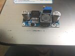
I am powering my router from 24V battery. But power requirement of router is 12V/1A. So I am using LM2596 buck converter.

The specification for this buck converter is as follows:

Input voltage: 4-40V

Output voltage: 1.2-37V
WhatsApp Image 2018-08-17 at 16.09.58.jpeg

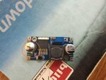
Scenario 1:

It worked fine for a day. Next day when I connect a battery output to buck converter input, input capacitor started to burst(No output is connected). What might be the cause for this behaviour?
WhatsApp Image 2018-08-20 at 15.35.21.jpeg

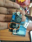
Scenario 2:

I bought another and tested it. The input which I provided is 24V and the output obtained is 12V. I connected the output to router. When I powered the router button on, voltage regulator emiited smoke and fired up.

What might be the cause for this behaviour?
WhatsApp Image 2018-08-20 at 15.37.33.jpeg

What should I need to do to overcome this?
 

To get that much damage I would suspect a reversed polarity somewhere. Is it possible you have a voltage at the output but not at the input? For example, is there a large capacitor holding charge at the output that feeds 'backwards' to the regulator when the input is disconnected.

If that is the case, connect a diode (1N400x series) between the +output and +input (I think the negative sides are linked on the PCB already) with the cathode toward the input connection. The diode will do nothing in normal operation but will prevent reverse polarity across the regulator if the input is removed.

Note that those boards should be screwed down to a heat sink through the holes provided and with a thermal pad beneath it so the tracks can't short to the heat sink surface.

Brian.
 
Excessive ripple current on the input causing the under rated cap to overheat and fail - the 2nd one looks like reverse polarity or faulty / fake buck chip ...
 
Excessive ripple when it's powered from a 24V battery :thinker:

There shouldn't be ANY ripple from a battery source, assuming it isn't being charged with 'dirty DC' at the same time of course.

Brian.
 

@ Brian, buck converters draw ripple current, square wave blocks of current, the local cap supplies much of this as a battery is high Z at high freq, if the cap is not rated it will over heat.

Fake components are a real headache in the west pacific region
 

I agree but generally, the low-Z of a battery source, unless long wiring is used, should be sufficient. To be honest, I was thinking of the 24V either being a battery charger or a battery under charge so AC line ripple was present. It takes quite a lot of current to explode a cap like that. If HF ripple from it's own switcher is the problem, a good quality non-electrolytic capacitor across the input should help.

I use a bank of five very similar modules in a multi-output PSU here but I have them mounted on a heat sink side by side with a thermal pad under them. They have been working for more than two years without any problems. One float charges a Pb battery, one powers a CPU module and the others power cameras and various AC control modules.

Brian.
 

If there is a cap at the switcher - it will supply the pulsed current (or try to) not the battery, esp at 50kHz-100kHz, I note in the above you say similar...

The parts are supposed to have over temp protection - but clearly in the photo above it died - so either fake or faulty or reverse DC in.

I agree about the heatsinking - many noobies are not familiar with the need.
 

I agree but generally, the low-Z of a battery source, unless long wiring is used, should be sufficient. To be honest, I was thinking of the 24V either being a battery charger or a battery under charge so AC line ripple was present. It takes quite a lot of current to explode a cap like that. If HF ripple from it's own switcher is the problem, a good quality non-electrolytic capacitor across the input should help.

I use a bank of five very similar modules in a multi-output PSU here but I have them mounted on a heat sink side by side with a thermal pad under them. They have been working for more than two years without any problems. One float charges a Pb battery, one powers a CPU module and the others power cameras and various AC control modules.

Brian.

Ya it's a battery being charged. How do I check for high frequency ripple?

WhatsApp Image 2018-08-17 at 16.26.55.jpeg

What do you think of scenario 2?

Did router draw too much current ?
 

You need an oscilloscope to check for HF ripple.

I tried to find a specification for that battery but every reference to it just asks me to request a price quote. I can not find any reference to the voltage or charging characteristics except for one that looks the same but says it is 12V.

When you say "Ya it's a battery being charged. How do I check for high frequency ripple?" do you mean it is connected to a charger at the time the PSU burns? A charger normally doesn't produce 'clean' DC, their output is rectified AC without any filter and normally at a higher peak voltage than the battery they are charging. If the charger is connected, you must remove it from the battery before using your PSU board.

Brian.
 

All the HF switching ripple will be caused by the buck chip on the pcb, if you add a decent electro cap as suggested above you may avoid more input electro's on the pcb going bang ... good luck ...
 

possibly the scenario is two buck converters in series, one charger with load and another converter with a router load, that could be the reason input capacitor blew up. more filtration is required, or run long wires from the battery to the second controller, or even keep a small resistor in series.
 

Status
Not open for further replies.

Similar threads

Part and Inventory Search

Welcome to EDABoard.com

Sponsor

Back
Top