Continue to Site

Welcome to EDAboard.com

Welcome to our site! EDAboard.com is an international Electronics Discussion Forum focused on EDA software, circuits, schematics, books, theory, papers, asic, pld, 8051, DSP, Network, RF, Analog Design, PCB, Service Manuals... and a whole lot more! To participate you need to register. Registration is free. Click here to register now.

How to find characteristic impedance of microstrip with an unknown substrate?

Status
Not open for further replies.

Luckyer

Newbie level 3
Newbie level 3
Joined
Feb 23, 2018
Messages
3
Helped
0
Reputation
0
Reaction score
0
Trophy points
1
Activity points
27
Hi all,

I probably have a simple question.

I have to design a circuit with a multilayer substrate which i cannot know his real permitivity nor other parameters but dimensions, I can just use it to my simulations and momentum.

But i need to make a 50 Ohms / 90º microstrip line. After doing the simulations and obtaining the S parameters, how could I obtain Z0 just with S parameters?

I put a 50 Ohm load at the line and made the Z0 = ZL (1-S(1,1))/(1+(S(1,1)) relation with a known line and substrate (W and L for 50 Ohm and 90º), but I can't obtain feasible results (Z0 = 0.2 < 80º)

Thanks ! :)
 

Hi,

I have to design a circuit with a multilayer substrate which i cannot know his real permitivity

If you have to design it then:
* either you need to know it
* or you need to specify it

--> Discuss this with your PCB manufacturer

Klaus
 
I may explained wrong.

I get the substrate specifications, but is multilayer, so I have differents permitivities for each layer but its behaviour is different all together. I did the momentum simulation of a kind of 50 Ohm / 90º degrees line (based on a medium of all layers permitivities, but it isnt the real permitivity) and obtained the S Parameters.

Now i want to know if its really 50 Ohms / 90º degrees, with the objetive of knowing how far of it is it and how to correct it later.

In conclusion, know the Zc and electric length of a microstrip line based on just the S parameters.

Thanks anyway!
 

After doing the simulations and obtaining the S parameters,
how could I obtain Z0 just with S parameters?
Convert S={S11, S12 ; S21, S22} to F={A, B ; C, D}.

You can get Z0=sqrt(B/C).

2*pi*Length/Lambda=acos(A)=acos(D)
 
Last edited:
Nice! It worked like a charm. Now i think i could work with any substrate if i cant know its real permitivity.

Thanks!! :)
 

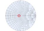
What i do...i take my simulation of the thru transmission line, plot S11 on a smith chart and sweep the frequency from say 1 to 10 GHz. It will draw a small circle on the smith chart, and the CENTER of that circle is the characteristic impedance of the line.

40 ohm line.PNG

So this is showing a 40 ohm characteristic impedance line (assuming your simulation ports were 50 ohms).

Is that what you were asking?
 
Last edited:
Status
Not open for further replies.

Part and Inventory Search

Welcome to EDABoard.com

Sponsor

Back
Top