Continue to Site

Welcome to EDAboard.com

Welcome to our site! EDAboard.com is an international Electronics Discussion Forum focused on EDA software, circuits, schematics, books, theory, papers, asic, pld, 8051, DSP, Network, RF, Analog Design, PCB, Service Manuals... and a whole lot more! To participate you need to register. Registration is free. Click here to register now.

Why the door ring can't work?

Status
Not open for further replies.

tony_lth

Advanced Member level 5
Joined
Jul 28, 2010
Messages
2,098
Helped
377
Reputation
756
Reaction score
369
Trophy points
1,363
Location
Beijing
Activity points
12,727
Hi, Gurus,
I want to spend some time with my son together, so we decided to make a door ring.
We bought a raw PCB and mated RLC from a shop in Taobao.
Unfortunately, after we soldered all the components on the PCB, the door ring can't work.
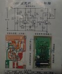
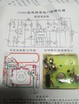
Attachments are TX, RX, and one ppt for soldering the components respectively.
Who can help?

- - - Updated - - -

And I found some:
1. When I pressed the TX button, the tx part green LED is on, but the RX can't alarm, so I guess TX is OK , RX isn't.
2. When I used multimeter D1 4148 (between U1 CD4069 pin9 and pin10), forward then backward, then the RX alarm ring even without TX on.
Forward is multimeter red on D1 4148 anode, and black on cathode.
Backward is multimeter black on D1 4148 anode, and red on cathode.
 

Attachments

  • Door Ring Receiver2.jpg
    Door Ring Receiver2.jpg
    496.8 KB · Views: 187
  • Door Ring Transmit2.jpg
    Door Ring Transmit2.jpg
    53.1 KB · Views: 182
  • Door Ring Soldering PPT.pdf
    1.3 MB · Views: 186

I see nothing in the receiver schematic to allow you to tune its radio frequency to the radio frequency of the transmitter.
The green LED lights when the transmitter has a power supply voltage and has nothing to do with the transmitter circuit so the transmitter might not be working.
The radio parts of the receiver also might not be working.
 
Hi, Audioguru and ALL,
In TX part, there is a inductor/T1/2.5T, which can be tuned to tune the freq.
But I used a screw to tune it, the door bell still not works.
For the RX, there is a inductor L1/3.5T, which can tune the gaps between the turns to tune the freq, still not works.
 

This circuit should work at 32.768KHz, right?
So who can explain antenna circuit? The filter and the TX power?

- - - Updated - - -

If I replace TX R2 39K with 1K, then the TX power on antenna should be much higher, right?

- - - Updated - - -

R7=100K, could the crystal circuit work?

- - - Updated - - -

At R2 two terminals, I should see the 32.768K waveform with osciloscope, right?
[I should rent a 2nd hand osciloscope from someone]
 

32kHz is an AM (OOK) modulation frequency, not the RF carrier.

If I replace TX R2 39K with 1K, then the TX power on antenna should be much higher, right?
Or the power dissipation blows the transmitter transistor, who knows?

R7=100K, could the crystal circuit work?
Possibly. I don't see much sense in reengineering this rather power design. At best you can use an oscilloscope and appropriate tools for the RF part to verify the circuit operation step by step.
 
Ok, FvM,
Since it's a OOK, so when ON, the antenna can see the 32.768 carrier. I can test this to verify.

- - - Updated - - -

Q3 and Q2 and crystal is the osc circuit, and Q1 is the amplifier, right?
So I can remove C2/C1/C4, and even no need to tune T1, right?

- - - Updated - - -

Sorry, I checked the circuit again, C1/C2/C4 are antenna tuner.

- - - Updated - - -

So this door rong may work at 32.768K harmonics, and C2/T1 is a bandstop filter for selecting TX filter, other harmonics should be grounded.
 

It almost certainly works at 433MHz not 32.768KHz, you are confusing the carrier and the modulation frequency.

Most systems work by sending a coded string of pulses at UHF which are recognized by the receiver but this design uses a modulated tone. Without some kind of recognizable feature the receive would respond to everything using the frequency, car remote locking, weather station and similar.

The transmitter is just a 32KHz oscillator modulating a UHF oscillator.
The receiver is a supregenerative detector feeding two stages of 'linear' amplification in the CD4069, another resonator to select only 32KHz, then further stages of amplification with D1 recovering the envelope to trigger the sound.

Check the voltage across C10 in the receiver and see if it increases when the transmitter is turned on. If it does, the fault is around U2/Q3. If it doesn't change, measure the AC voltage at pin 2&3 of U1 and report back what you see.

Brian.
 
Hi, Brian,
Nice to get your comment.
The voltage across C10 doesn't change when turning on TX.
The AC voltage at pin2&3 and GND is 1.73V with 160Hz, and sometimes the freq is decreased to 40Hz, but the AC voltage is still 1.73V.
I measured with multimeter, the AC voltage option.
I observed that the AC voltage is 0.4V/50Hz, which is the AC power supply of my home, when multimeter two probes are open.
What is next step?
Many thanks.
Best,
Tony Liu

- - - Updated - - -

U1 pin2 and pin3 is linked directly.
 

Did you actually make a Correct PCB's for this?
The On-Board coil Traces will Quite critical.

I suspect that the L1 coil on the receiver is used to tune it to the transmitter frequency.
(By Slightly Expanding or Contracting that "L1" Coil.)

I Don't see any Value for L2?

- - - Updated - - -
 
Last edited:

What is that SD001?
I Suspect a Driver for the transistor, but I can't find it on Google?
 

More diagnostics, it is always difficult to find problems when there are two modules and you can't be sure which or both is at fault:

Measure the receiver voltage (DC range) at the junction of R3 and C6 to the negative side of the battery. Then with the transmitter with about 1m of the receiver, turn the transmitter on and off to see if there is a small voltage change. It will probably only be 0.1V or so but you should see it reliably change between the transmitter working and powered off.

If the voltage changes, the transmitter is probably working. If you don't see any change do this:

On the transmitter, measure the AC voltage on the collector of Q3 with respect to battery negative. Then temporarily short together the base and emitter of Q2 and see if the voltage changes.

If it does change, let me know the voltages on all pins of transmitter Q1 with respect to battery negative.

Brian.
 
Hi, chemelec,
Yes, L1 coil can be tuned by changing the gaps. And the SCH and PCB surely doesn't note the value for L2, just said it is a magnetic core inductor.

- - - Updated - - -

Hi, Audioguru,
Next week I will borrow one oscilloscope to test it.

- - - Updated - - -

Hi, chemelec,
SD001 is just a type of the door ring, which I bought from Taobao, one web shop in China. I think that SD001 may be named by them freely.
The seller said that the door ring can work.

- - - Updated - - -

Hi, Audioguru,
Yes, the SD001 plays "ding dong" and then plays "please open the door" in Chinese.
I said in post1 that I can trig the door ring sound with multimeter, by forward test and backward test.
 

Hi, Brian,
Many thanks.
The RX R3/C6 DC voltage no change, about 1.01V, when the transmitter working and powered off.

- - - Updated - - -

Hi, Brian,
The AC voltage on the collector of Q3 with respect to battery negative is 0.97V, and when temporarily short together the base and emitter of Q2, the Q3 collector voltage NO change.

- - - Updated - - -

Hi, Brian,
I measured with AC range of multimeter, not oscilloscope, and the multimeter displayed the AC freq is 10Hz.
Maybe I should tested with oscilloscope next week when I borrowed it.
 

Hi, Brian,
I tested with oscilloscope, Q3 collector voltage is about 90mV@T=4us. When shorting together Q2 B and E, Q3 collector voltage changed to 6mV@no period.
So Q3 C voltage changed.
V_E_Q1=0V
V_B_Q1=0.39V
V_C_Q1=10.5V
Any comment?
Thanks.
Best,
Tony Liu
 

I just followed the thread, checked the comments and hope you'll find the solution from betwixt discussions. One piece I would suggest is to assemble the circuit prototype on breadboard (wheneever possible) for avoiding the prospective hassle.
 

I would have expected more like 1V of signal on Q3 collector and the period should be about 30uS. I would guess the 32KHz oscillator isn't running at all and the small 4uS signal is pick-up from somewhere else, possibly a strong AM radio station. 4uS suggests around 250KHz frequency.

It is a simple circuit so perhaps it would be easiest to to post all the voltages at each component junction for the transmitter and the receiver. Maybe draw the voltages on top of the pictures to keep it easy to understand.

I would suggest is to assemble the circuit prototype on breadboard
The coil and layout of the PCB are part of the circuit tuned circuit - it almost certainly wouldn't work at all if the PCB layout was changed or it was built on breadboard.

Brian.
 
I just followed the thread, checked the comments and hope you'll find the solution from betwixt discussions. One piece I would suggest is to assemble the circuit prototype on breadboard (wheneever possible) for avoiding the prospective hassle.
A solderless breadboard has high stray capacitance between all the rows of contacts and wires all over the place so it probably will not let the high VHF or UHF circuit work.
 
Status
Not open for further replies.

Part and Inventory Search

Welcome to EDABoard.com

Sponsor

Back
Top