musmanm
Member level 2

Hello everyone!
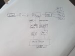
I want to design a return loss measurement system. I will connect an RF resonator and measure its return loss. The block diagram for such measurement setup is attached with this post.
I also want to use the chip (directional coupler and VCO) to miniaturize the size of RF measurement system.
For design such setup, which computer simulation tool do you recommend? And, for the MCU/FPGA part, is it possible to have an LCD display right on the board showing the return loss for every single frequency?
I am not an expert in circuit designing and microprocessor. I am an electromagnetic guy, so the RF resonator part is my major contribution to this project, but again, I also want to design this system.
I will be grateful if anyone can give me the direction and advise of how to start working on it.
Thank you!
Please see the return loss measurement block diagram.

- - - Updated - - -
The reonant frequency of the RF resonator is 4.5 GHz
I want to design a return loss measurement system. I will connect an RF resonator and measure its return loss. The block diagram for such measurement setup is attached with this post.
I also want to use the chip (directional coupler and VCO) to miniaturize the size of RF measurement system.
For design such setup, which computer simulation tool do you recommend? And, for the MCU/FPGA part, is it possible to have an LCD display right on the board showing the return loss for every single frequency?
I am not an expert in circuit designing and microprocessor. I am an electromagnetic guy, so the RF resonator part is my major contribution to this project, but again, I also want to design this system.
I will be grateful if anyone can give me the direction and advise of how to start working on it.
Thank you!
Please see the return loss measurement block diagram.

- - - Updated - - -
Hello everyone!
I want to design a return loss measurement system. I will connect an RF resonator and measure its return loss. The block diagram for such measurement setup is attached with this post.
I also want to use the chip (directional coupler and VCO) to miniaturize the size of RF measurement system.
For design such setup, which computer simulation tool do you recommend? And, for the MCU/FPGA part, is it possible to have an LCD display right on the board showing the return loss for every single frequency?
I am not an expert in circuit designing and microprocessor. I am an electromagnetic guy, so the RF resonator part is my major contribution to this project, but again, I also want to design this system.
I will be grateful if anyone can give me the direction and advise of how to start working on it.
Thank you!
Please see the return loss measurement block diagram.

The reonant frequency of the RF resonator is 4.5 GHz


