Garyl
Full Member level 5

Hello again!
I am still studying various receivers projects and now I've stumbled upon the hs8jyx creation described here:
https://hs8jyx.blogspot.com/2013/08/ssbcw-7-mhz-fine-tune.html
From what I see it's a simple receiver for 7MHz (40m) band, which should be able to receive something at night.
This is the schematic:

The PCB and connections diagram:

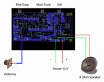
PCB PDF:
View attachment 7mhz-pcb.pdf
Description (translated by Google Translate):
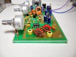
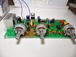
Photos of original circuit made by author:

And now, I want to replicate this circuit but I have several questions:
1. Is this diode correctly connected? It looks like a direct connection to ground, but well, it's at the gate of the MOSFET...

2. The tuning circuit - are they using 1N4001 diode as varicap?
3. The tuning circuit - from what I see, I can start that VFO without NE602 for testing on the separate board? I will measure frequency with oscilloscope...
4. The tuning circuit - is the 2N3819 JFET crucial here or can I use other MOSFET or even BJT?
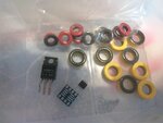
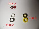
5. How crucial are those toroids, listed as "T37-2", "T50-7", "T50-6"? Can I get it working with the "no name" toroids from the electronic waste?
6. Why can't I just use a normal 1.5uH axial trough-hole inductor 1.5uH in the double pass filter? Is this related to current issues or what? Does it really have to be 19 turns T37-2 (red core)?
7. There is LM386 connected to the TDA2030 by potentiometer. They are both audio amplifiers, then, why are there two amplifier stages used? Is this justified in this circuit, or is this just for... louder sound?
8. What kind of antenna do I need for that receiver? Does it have a good sensitivity?
I am still studying various receivers projects and now I've stumbled upon the hs8jyx creation described here:
https://hs8jyx.blogspot.com/2013/08/ssbcw-7-mhz-fine-tune.html
From what I see it's a simple receiver for 7MHz (40m) band, which should be able to receive something at night.
This is the schematic:

The PCB and connections diagram:


PCB PDF:
View attachment 7mhz-pcb.pdf
Description (translated by Google Translate):
The 7MHz SSB / CW radio receiver has a Fine Tune
First of all, thanks to your fellow members for your interest in this project. This project is the same circuit as the 14 MHz version (https://hs8jyx.blogspot.com/2013/06/14-mhz-vfo.html), but we made a new circuit board to simplify the sealing box. For a frequency of 7 MHz the frequency is quite constant. There is no frequency slider so much that I can not accept it.
The 7 MHz frequency will be able to communicate well in the night. Members who have not played this frequency yet. Do not be surprised if the day can not get anyone. Or get a strange noise.
Download the PCB at https://drive.google.com/file/d/0BxgJ9QX1BWUyWnBVbE1BSlJfR1E/edit?usp=sharing.
1.5 uH coil using 19 copper coil on T37-2 (red) coil (round counter of spindle https://15meter-radio.blogspot.com/2013/02/toroid.html )
The L1 coil can be wrapped around 21-22 on T50-7 or 22-23 on T50-6 (this is because the coil can be squeezed or loosened. Number of rounds can change a little)
(Example of reception I do not have a 7 MHz antenna. Use a long cable instead of an antenna.) Figure down the device and the connection.
Wide Bandwidth - Narrow What determines
From the figure is our VFO circuit. Adjusting the frequency of the VFO circuit can be done in two ways: adjust the L (coil) and adjust the C (capacitor). Here we use the C modulation using the capacity. At 1N4001 diodes, the higher the voltage range, the wider the bandwidth. (Ie 0-8 volts is wider than 0-5 volts, for example).
C2 and C3 also determine the bandwidth. up to a certain point, it does not matter L1 C1 will affect Bandwidth much. That if I Bandwidth widened to the L1 high value C1 less (frequency remains the same, but Bandwidth increases ) that this is coming from the C in the diode will affect the frequency, if connected to a C. a few examples receiver 7.1 MHz (to practice it), we assume a diode 1N4001 in tune with the 2-25 pF (by tuning voltage maximum and minimum).
Frequency Resonance Formula
Circuit 1 uses a low coil (using 1uH). We need to use a C value of 502 pF (500pF + 2 pF of the smallest diodes) to obtain a 7.1 MHz frequency.
At the lowest voltage, we get a frequency of 7.100 MHz ( 1uH // 500 + 2pF)
when the maximum pressure is not frequency MHz is 6.950 (500 +, 1uH // 25pF)
a bandwidth = 150 KHz,
the circuit uses two coils over (use 2 uH)
we need to use the C 502 pF (. 249pF + 2 pF diode, as a minimum) to 7.1 MHz frequency
when the minimum voltage to frequency 7.100 MHz (1uH // 249 + 2pF
p. When the maximum voltage, we have a frequency of 6.800 MHz (1uH // 249 + 25pF) Bandwidth = 300 KHz
Photos of original circuit made by author:


And now, I want to replicate this circuit but I have several questions:
1. Is this diode correctly connected? It looks like a direct connection to ground, but well, it's at the gate of the MOSFET...

2. The tuning circuit - are they using 1N4001 diode as varicap?
3. The tuning circuit - from what I see, I can start that VFO without NE602 for testing on the separate board? I will measure frequency with oscilloscope...
4. The tuning circuit - is the 2N3819 JFET crucial here or can I use other MOSFET or even BJT?
5. How crucial are those toroids, listed as "T37-2", "T50-7", "T50-6"? Can I get it working with the "no name" toroids from the electronic waste?

6. Why can't I just use a normal 1.5uH axial trough-hole inductor 1.5uH in the double pass filter? Is this related to current issues or what? Does it really have to be 19 turns T37-2 (red core)?
7. There is LM386 connected to the TDA2030 by potentiometer. They are both audio amplifiers, then, why are there two amplifier stages used? Is this justified in this circuit, or is this just for... louder sound?
8. What kind of antenna do I need for that receiver? Does it have a good sensitivity?


