Continue to Site

Welcome to EDAboard.com

Welcome to our site! EDAboard.com is an international Electronics Discussion Forum focused on EDA software, circuits, schematics, books, theory, papers, asic, pld, 8051, DSP, Network, RF, Analog Design, PCB, Service Manuals... and a whole lot more! To participate you need to register. Registration is free. Click here to register now.

[SOLVED] Audio Signal Coupling Capacitor

Status
Not open for further replies.

dreamlover

Member level 2
Member level 2
Joined
Jan 13, 2015
Messages
47
Helped
14
Reputation
28
Reaction score
14
Trophy points
1,288
Activity points
1,610
While searching on internet for 10W audio amplifier, i found a circuit using 4 transistor shown bellow.
Now my question are
1. Is the value of coupling capacitor (c1) is appropriate for working with audio input signal?
2. If the value is enough to couple then how to calculate the value of capacitor (c1).
Note: According to my calculation the range of capacitor could be of few microfarad, but according the the given value in circuit diagram the it only passes signal above few KHZ frequency.
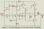
Circuit Diagram of 10 watt Audio Amplifier.jpg
 

Your calculations are correct, C1 isn't suited for audio frequencies.

The schematic has several other flaws, looks like defective copy and paste of a previously working circuit. Hands off.

I have seen germanium transistors AC187/AC188 in audio amplifiers designed 50 years ago. I wonder where the schematic has been digged out.
 

I concur.

I don't think that would ever work and the chances of anything remotely like 10W from it are very slim with those output transistors. Quite aside from wrong (or missing) bias conditions ands some strange capacitor values, the output transistors are only rated for 25V and 0.3A maximum. That is assuming you can find matched pairs of 40 year old transistors of course!

Brian.
 

hi,
LTSpice sim frequency responseof your original circuit, it is awful, with a 220uF in place of the 220pF, still awful.

I agree with fvm, the circuit wrong and well out of date.

E
 

Attachments

  • A04.gif
    A04.gif
    25.2 KB · Views: 230
  • A05.gif
    A05.gif
    24.8 KB · Views: 228

Germanium transistors have very significant leakage currents which severely increase with temperature. The schematic, as shown, has no provision to change the output transistor's biasing with temperature.

This is clearly not a well thought-out design.
 

I'm not convinced T4 ever conducts anyway. I haven't done any calculations or simulation but it seems to be lacking any bias source. That probably doesn't matter much anyway as R4 will somewhat limit the volume it can produce!

Brian.
 

Emitter of T1 is short circuit for AC signals bur there is a feedback by R5//C4 that will never work..
It's absolutely a fake circuit.. It doesn't make sense to analyze..
 

The website where the awful OLD schematic came from is in Nepal that is on the northern edge of India. The website is run by students.
 

Others have already pointed out flaws in the design, so I won't go into that.

Germanium devices have many disadvantages compared to Silicon - they can endure only half the temperature and they are leaky and slow. But they also have some advantages too: They have a more linear gain and lower saturation voltage and this makes them well suited for low voltage audio amplifiers. For less than hi-fi designs, biasing them for Class AB operation is less critical because they have a lower and more gradual breakover Vbe knee (this is solely my own opinion. Others may disagree).

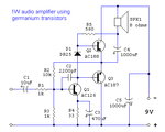
I have fond memories of the AC187/188 pair as I based some of my early solid-state amplifier designs on them back in the 1970s. I built several of them for myself and for others. The circuit below is one example that worked well.

1W_amp.png

P.S.: I used to have very detailed printed datasheets for those old devices but I've misplaced them. These days, I can find only short-form single-line listings. These abbreviated data usually give the maximum current rating of these devices as 300mA but, unless my memory is playing tricks on me, they were 500mA continuous and 1A peak.
 
Last edited:

Pj;:smile:

you have also drawn the schematic the way that the original germanium transistor schematics were originally drawn: with the ground (common) being the battery's positive.
 

That's right. This is not something I've just drawn; it's one of my actual designs from those early days that I put into digital form as soon as I had a personal computer.

It was common for radios and amplifiers to be dominated by PNP types, with NPN types used only where necessary. It was only natural to use the positive rail as ground.
 

Hi,

Intersting detail. Indeed all the circuit seems to be "+ suplly" referenced,
but not the speaker...

Since the late 90s I've build a couple audio amplifiers. For fairly good quality I always used ICs.
Only for extraordinary sound quality I used discrete parts.
In my eyes none of the shown circuits have a benefit against ready to buy audio amplifer ICs.
Cost, quality, effort...

Klaus
 

Hi, I was reminiscing about late 1960s and early 70s technology. There were few audio amplifier ICs back then and those that existed were not easily available in some places. They often needed almost as many external components as discrete designs and in some cases actually cost more than an all-discrete design.

Another factor was inertia. Some companies and hobbyists were simply more familiar with discrete components than with ICs and were reluctant to change. And, by the standards of the time, ICs offered a more restricted choice of component placement in PCB designs.

Yet another factor was low voltage operation. For example, my circuit above had no problem running from 3V with only minor changes. As far as I know, an equivalent IC did not exist then.

Intersting detail. Indeed all the circuit seems to be "+ suplly" referenced,
This was rather spectacularly demonstrated in one incident. We were making a street announcement of an upcoming concert, slowly cruising in a Jeep while using its battery to power the P.A. amplifier. The positive chassis of the amplifier came in contact with the Jeep's negative body, causing a short circuit. Sparks flew for a couple of seconds before I realised what was happening and pulled the amplifier away.
 

The speaker is not referenced to the positive ground because it forms bootstrapping. The output at the speaker pushes up the base drive to the PNP output transistor to a max voltage that is above the negative supply voltage for a wider voltage swing (for more max output power). Usually an extra resistor and capacitor form bootstrapping like this:
 

Attachments

  • bootstrapping.png
    bootstrapping.png
    27.1 KB · Views: 524
That's correct. This was a minimal design that worked well enough for its intended use. Using the speaker and the output coupling capacitor for bootstrapping saves two components which is significant, given the low overall component count. Not referencing the speaker to ground doesn't matter for small battery-operated gadgets. The DC current through the voice coil is too low to cause audible distortion.

It had no pretension of being hi-fi but sounded quite good to the average ear - no glaring distortion. Sometimes I included a single transistor RF stage fixed tuned to the local AM radio station. Not superhet but I usually included AGC.
 

I listened to the awful muffled, distorted and interference sounds on AM radio stations about 60 years ago. I still have some of the germanium transistors I used. About 55 years ago I built a kit hifi FM tuner then a few years later I built a kit stereo adapter for it and the wide bandwidth, low distortion and no interference sounds were wonderful.
A few years ago when I discovered that my hearing has severe high frequency loss that is normal for my age (72 in a few days) I got hifi hearing aids that make my hearing young again and they have some features that normal hearing cannot do.
 

Status
Not open for further replies.

Similar threads

Part and Inventory Search

Welcome to EDABoard.com

Sponsor

Back
Top