juanMco
Newbie level 6

Hello everyone!
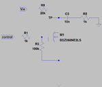
I am having some trouble with a charging/discharging capacitor circuit. Here I attach the basic circuit:

The "control" signal is a square wave from a 555 timer with period T=10 ms and TH= 250 uS to set up the switching for the transistor. "Vin" is the charge voltage for the capacitor (2 V in this simulation) and R9 sets the RC constant.
I need to charge/discharge the 10nF capacitor to generate a pulse (the original circuit has another capacitor to do the discharge pulse). When simulating the circuit with commercial transistors (NMOS and BJT), I see some peaks on the voltage exactly on switching times (testing on TP).

I need to reduce this peaks to ZERO or uV range. What kind of changes can I do on this circuit? I tried a lot of different transistors with low parasitic capacitances values but these peaks are always there. Thanks in advance.
Regards.
I am having some trouble with a charging/discharging capacitor circuit. Here I attach the basic circuit:

The "control" signal is a square wave from a 555 timer with period T=10 ms and TH= 250 uS to set up the switching for the transistor. "Vin" is the charge voltage for the capacitor (2 V in this simulation) and R9 sets the RC constant.
I need to charge/discharge the 10nF capacitor to generate a pulse (the original circuit has another capacitor to do the discharge pulse). When simulating the circuit with commercial transistors (NMOS and BJT), I see some peaks on the voltage exactly on switching times (testing on TP).

I need to reduce this peaks to ZERO or uV range. What kind of changes can I do on this circuit? I tried a lot of different transistors with low parasitic capacitances values but these peaks are always there. Thanks in advance.
Regards.

