Continue to Site

Welcome to EDAboard.com

Welcome to our site! EDAboard.com is an international Electronics Discussion Forum focused on EDA software, circuits, schematics, books, theory, papers, asic, pld, 8051, DSP, Network, RF, Analog Design, PCB, Service Manuals... and a whole lot more! To participate you need to register. Registration is free. Click here to register now.

LCD and pic not comunication

Status
Not open for further replies.

Alberto Dan

Junior Member level 3
Joined
Jun 5, 2014
Messages
26
Helped
0
Reputation
0
Reaction score
0
Trophy points
1,281
Activity points
1,584
Hy i have a problem and and don't uderstand why is not work.i connect a pic 16f628A on LCD 16x2 1602A,I use microK to write the code and pickit3 to send code on pic.After i upload the code on PIC the LCD just stay open,the message not apear on it.What i can do?The code is below:
Please i need help!


Code C - [expand]
1
2
3
4
5
6
7
8
9
10
11
12
13
14
15
16
17
18
19
20
21
22
23
24
25
26
27
28
29
30
31
32
sbit LCD_RS at RA0_bit;
 sbit LCD_EN at RA1_bit;
 sbit LCD_D4 at RB4_bit;
 sbit LCD_D5 at RB5_bit;
 sbit LCD_D6 at RB6_bit;
 sbit LCD_D7 at RB7_bit;
 sbit LCD_RS_Direction at TRISA0_bit;
 sbit LCD_EN_Direction at TRISA1_bit;
 sbit LCD_D4_Direction at TRISB4_bit;
 sbit LCD_D5_Direction at TRISB5_bit;
 sbit LCD_D6_Direction at TRISB6_bit;
 sbit LCD_D7_Direction at TRISB7_bit;
// End LCD module connection definition
// Define Messages
 char message1[] = "Welcome to";
 char message2[] = "My world";
 void main() {
  //ANSEL = 0b00000000; //All I/O pins are configured as digital
  CMCON = 0x07 ; // Disbale comparators
  TRISB = 0b00000000; // PORTC All Outputs
  TRISA = 0b00000000; // PORTA All Outputs, Except RA3
  Lcd_Init();                      // Initialize LCD
  do {
   Lcd_Cmd(_LCD_CLEAR);             // CLEAR display
   Lcd_Cmd(_LCD_CURSOR_OFF);        // Cursor off
   Lcd_Out(1,4,message1);            // Write message1 in 1st row
   Lcd_Out(2,1,message2);           // Write message2 in 2nd row
   Delay_ms(1000);                       // Wait for 1 sec
   Lcd_Cmd(_LCD_CLEAR);     // Clear display
   Delay_ms(1000); // Wait for 1 sec
  } while(1);             // Infinite Loop
 }

 
Last edited by a moderator:

Do you mean, it is not working on simulation, or real world ?
Where is the schematic, are you sure proper connections were made ?
 

The code looks reasonable assuming LCD_init() does actually initialize it.
Are you seeing anything at all on the LCD and if not, do you have the bias control (aka "contrast") pin connected ?

Brian.
 

I know why it is not working. He either doesn't have a Crystal Oscillator or if he has one say 4 MHz then in project settings it is set to HS instead of XT.
 

I know why it is not working. He either doesn't have a Crystal Oscillator or if he has one say 4 MHz then in project settings it is set to HS instead of XT.
That is one of many possible reasons. Lets wait for Alberto Dan to report back before jumping to conclusions.

Brian.
 

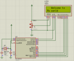
I atache a schematic.The only differences from real schematic is that the LCD have an Anode who it's connect from a resistor at VDD an an Cathode connected on VSS(pin 15 and 16).In proteus simulation it's work but in real implementation it's not work.I selected on mikroc tool "XT" and "HS" and still not worked.Just stay LCD lights.I don't know what to do !I need help! PIC16f628A.PNG
 

Try another display. Maybe display is defective.
 

In proteus simulation it's work but in real implementation it's not work.

Are you sure that the display that you're using on "real world" has the same controller IC of the module used on simulation ? There are variants from distinct manufacturers ( Samsung, Hitashi, ... ) for which the bit banging 'protocol' varies.
 

The LCD model is RG1602A by from aliexpress.Model RG1602A.link is below **broken link removed**
 

Check (See edited to Check) if you shorted any pins of the LCD while soldering.
 
Last edited:

Post datasheet of LCD.

- - - Updated - - -

Use code from post #14 here.

https://www.edaboard.com/threads/361841/

Maybe your display needs a longer strobe like the OLED display mentioned in above thread.

If it works then post hardware working pictures.
 

Hy can anyone help me?Please!!I try another display,i try with another PIC and is the same.No see nothing on display,just lights :((.I don't what to do!What i'm doing wrong?Can anybode help me!!
 

Start with basics.

If you angle the LCD slightly downwards from a direct line to your eyes, then turn the contrast control from end to end, do you see a 'shadow' of the character pixels? When the control is near the ground end of the adjustment you should see 'boxes' of all the 40 pixels in each character and they should disappear as you turn the control.

If you can't see them - either you have the LCD wired wrongly or the 'contrast' control is not working.

If you can see them and the control works, leave it set so the pixels are at about half contrast.

Now remove the direct connection between -MCLR and wire a 10K resistor in it's place. This will not stop the reset working but it will let you ground the -MCLR pin without shorting out the power rails. While looking at the LCD, try grounding -MCLR with a wire link and note if there is any change on the LCD. This will give some idea if the PIC and LCD are communicating. Let us know the results.

Brian.
 

I would start even further back...
Do you have bypass capacitors on the Vdd pin?
Can you 'flash a LED' on the device? This will show if the programming is working, the config settings are at least 'workable' and the oscillator is at the correct frequency. (Timing can be critical in getting the LCD to intialise.)
Can you run the code in 'debug' mode (this may require using different pins as the debugger will need RB6 and RB7)? This will also show that the oscillator is running and the code is actually executing.
Susan
 

If i reset PIC from MCLR nothing happend with LCD :(.What should be happened?If i adjust the contrast of LCD i see the pixels.I make the connection from LCD to PIC like in proteus schematics directly and i check this with a multimeter continuity and averything wa OK :(

- - - Updated - - -

No another display with other model and the result was the same :(
 

What should be happened?
What I was checking was the delay between the PIC powering up and the LCD powering up. When the supply is turned on, the LCD internal processor takes about 0.1 second to initialize before it will accept any commands. In your schematic, the -MCLR pin was conected directly to VDD so the PIC would inmnitialize immediately. There was a danger that the PIC sent commands to the LCD before it was ready to accept them. The very first commands to the LCD are to configure it and if those are missed, the LCD will never display anything. By resetting the PIC (pulling -MCL to VSS) after the LCD has powered up you would ensure the LCD was ready to operate.

As you are noticing, simulations make assumptions about other things being right, thats why many of us don't use them!

It appears that the problem you have is to do with the timing of commands to the LCD rather than the commands themselves or data connections. Those LCDs have critical timing requirements but the compiler should be able to take those into account for you. I suspect therefore that you have a configuration error in the compiler settings and the PIC isn't running at all or is running at the wrong speed. Make sure the settings for the clock frequency is the same as the crystal you are using and the clock type is set to XT for a crystal less than 4MHz and HS for a crystal of 4MHz or higher. Also disable the WDT (Watchdog timer) and enable the start-up timer.

Electrically, make sure the crystal and it's loading capacitors are close to the PIC and have short wires and ensure you have decoupling capacitors across the VSS and VDD pins, close to the PIC.

Brian.
 

I don't have bypass cap on the VDD.How run in the debag mode in mikroc?I try to flash a led and is OK.I try to put a bypass cap,but how can i make debag on mikroc tool?
 

It probably will not work without the decoupling capacitors. Connect a 10uF and 100nF capacitor in parallel and wire then across VSS and VDD as close to the PIC pins as you can manage.

In my opinion, MikroC debugging is next to useless. I doubt it will prove anything.

Brian.
 

Status
Not open for further replies.

Similar threads

Part and Inventory Search

Welcome to EDABoard.com

Sponsor

Back
Top