eengr
Member level 4

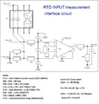
I have built a circuit to measure temperature using 2 wire RTD interface as shown below:

I am effectively using one half of the dual current source (100uA) as 2nd half is connected to 0V-GND (via R41 & R81 0 ohm links). The idea is to use this circuit with Pt-100 & Pt-1000 type devices. The output of amp is going to an ADC. The voltage divider at output (R44 & R45) is to cater for broad range of temperatures using Pt-100 & Pt-1000 with one circuit. I started observing some non-linearity so decided to do some test by connecting a variable resistor (1K) between RT_Pos & RTD_Neg termianls (RTD_Neg is effectively GND)
Using a DVM I took measurements for voltage drops and got the following results:
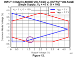
As you can see than somewhere between 812.5ohms & 830.3 ohms, the gain of amplifier started to drop and it carries on like this up till 1K+ input resistance . I am struggling to understand the reason for this behaviour of the amplifier. Am I overlooking any parameter in datasheet of the amplifier here? It is rated for Single Supply operation from 3V to 36V DC. I am using 5V DC as Rail. The amp has 1uF decoupling cap across its Rail (not shown on schematic) Any help would be greatly appreciated

I am effectively using one half of the dual current source (100uA) as 2nd half is connected to 0V-GND (via R41 & R81 0 ohm links). The idea is to use this circuit with Pt-100 & Pt-1000 type devices. The output of amp is going to an ADC. The voltage divider at output (R44 & R45) is to cater for broad range of temperatures using Pt-100 & Pt-1000 with one circuit. I started observing some non-linearity so decided to do some test by connecting a variable resistor (1K) between RT_Pos & RTD_Neg termianls (RTD_Neg is effectively GND)
Using a DVM I took measurements for voltage drops and got the following results:
| Resistance connected (ohms) | Voltage drop across resistance (Vin) | Voltage at INA826 Amplifier Output (Vout) | Gain (Vout / Vin) |
| 45.96 ohm | 4.596mV | 88.11mV | 19.17 |
| 323.2 ohm | 32.32mV | 619.4mV | 19.16 |
| 551.8 ohm | 55.18mV | 1.057 V | 19.15 |
| 677.5 ohm | 67.75mV | 1.2983 V | 19.16 |
| 771.8 ohm | 77.18mV | 1.4789 V | 19.16 |
| 812.5 ohm | 81.25mV | 1.556 V | 19.15 |
| 830.3 ohm | 83.03mV | 1.576V | 18.98 |
| 886.4 ohm | 88.64 mV | 1.6052 V | 18.109 |
As you can see than somewhere between 812.5ohms & 830.3 ohms, the gain of amplifier started to drop and it carries on like this up till 1K+ input resistance . I am struggling to understand the reason for this behaviour of the amplifier. Am I overlooking any parameter in datasheet of the amplifier here? It is rated for Single Supply operation from 3V to 36V DC. I am using 5V DC as Rail. The amp has 1uF decoupling cap across its Rail (not shown on schematic) Any help would be greatly appreciated


