Continue to Site

Welcome to EDAboard.com

Welcome to our site! EDAboard.com is an international Electronics Discussion Forum focused on EDA software, circuits, schematics, books, theory, papers, asic, pld, 8051, DSP, Network, RF, Analog Design, PCB, Service Manuals... and a whole lot more! To participate you need to register. Registration is free. Click here to register now.

[SOLVED] Measure DC current Using Shunt

Status
Not open for further replies.

M.Rehan

Full Member level 2
Full Member level 2
Joined
Feb 10, 2016
Messages
129
Helped
2
Reputation
66
Reaction score
33
Trophy points
28
Activity points
972
I want to measure Battery charging current (High-Side Current Sensing) with a shunt and op-amps(LM393).

Circuit Diagram and Formula

Suggestions?
 

(High-Side Current Sensing)

You'll need a device whose reference is the positive supply rail, and responds with linear measurements down to the mV. This requires a different type of op amp than the ones we're normally familiar with.
 
  • Like
Reactions: M.Rehan

    M.Rehan

    Points: 2
    Helpful Answer Positive Rating
What will be the circuit if I use precision amplifier
 

An LM393 is a dual comparator with inputs that do not work if their voltage is within 1.5V from its positive supply voltage, it is not a dual opamp.
A TL081 is a single, TL082 dual and TL084 quad opamp that have inputs that work at their positive supply voltage.
 
Can someone post schematic with formulas for high side Current sensing using op amp
 

A TL081 is a single, TL082 dual and TL084 quad opamp that have inputs that work at their positive supply voltage.
The TL081 data sheet states the the minimum CM range is ±11V with ±15V supplies.
It will work typically to +15V but, as you've often stated, you don't want to use "typical" values for a design.
 

The TL081 data sheet states the the minimum CM range is ±11V with ±15V supplies.
It will work typically to +15V but, as you've often stated, you don't want to use "typical" values for a design.
I think the printed spec's are wrong because the first page of the datasheet describes the feature that the "Common-Mode input voltage range includes VCC+". I guess because the input transistors are P-channel depletion-mode Jfets so they are still conducting when an input is at VCC+.
 

HI,

I recommend to use a dedicated "current sense amplifier". --> Cheap, precise, easy to use, all the formulas are in the datasheet, proven circuit.

Especially precision:
For an OPAMP solution you usually need very precise resistive voltage dividers and OPAMPs with low offset voltage (drift).


Klaus
 
I think the printed spec's are wrong because the first page of the datasheet describes the feature that the "Common-Mode input voltage range includes VCC+". I guess because the input transistors are P-channel depletion-mode Jfets so they are still conducting when an input is at VCC+.
Interesting.
So whoever wrote the first page of the data sheet apparently wasn't the one who wrote the spec's page.
I wonder which one is actually correct?
 

I simulated "Three Op Amp Instrumentation Amplifier" circuit in multisim and it is not giving varying output with current variation
Most likely reason you didn't observe OP common mode range.
 
  • Like
Reactions: M.Rehan

    M.Rehan

    Points: 2
    Helpful Answer Positive Rating
I have used same values of resisters and op amp given in reference notes with same voltage drop across shunt

junk3.PNG

I am new to this type of electronics so can someone explain me how I can use precision op amp for this purpose(Shunt ICS not available locally)

OR other way to measure shunt current with Transistor array (like ca3086 ) and op amp
Thanks
 

Thank You FvM

I will find op amp with common mode voltage range of 60 V and difference Mode voltage range of 10 V.

Any other parameter to account for measuring current at high side of 36V and 50A with voltage drop across shunt about 100 mV (max)
 

OR other way to measure shunt current with Transistor array

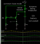
This method may be worth a try. The sense resistor is in the emitter leg of a PNP transistor (near the positive supply). Current through the sense resistor creates a proportional voltage. This voltage influences bias at the PNP, changing how much it conducts.

measure A sense resis at high-side w PNP.png

The transistor itself does not carry heavy current.

Careful adjusting of values is necessary, to get a semblance of linear response.
 

Dedicated current sense amplifiers have been already suggested.

Next best solution (in terms of accuracy) would be a regular OP with input common range including the positive rail, an auxiliary supply circuit, e.g. using a zener diode and a level shifter circuit.

cs amp.png
 

Current sense amplifier are not available locally:cry:

what should be Q1(pnp transistor) rating (breakdown voltage and current)
Is 1n4148 is ok for D1

Can this circuit be used for other direction in mirror configuration?
 

I suggest to calculate and adjust the circuit parameters (shunt voltage drop, transconductance of V/I converter) according to your project requirements and check it in a simulation.

D1 is a 10V zener diode, 1N4148 can't work in it's place. It's purpose is to drop the supply voltage to the range supported by the OP. Could be something between e.g. 5 and 15V, depending on the OP parameters. Consider that the current through R3 must be larger than the OP supply current. Q1 ratings are prescribed by circuit voltage and current. The example circuit is calculated for only mA IC, Vce0 should have some margin, e.g. using a 80 or 100V rated small signal transistor. As the Q1 current is proportional to shunt current, you should consider possible output overload in the calculation, or e.g. add a current limiting resistor between Q1 collector and R4.

The circuit has a positive output across R4, assuming you want to process the output voltage by an unipolar ADC. The mirrored configuration has a negative output, it might either use an additional inverting amplifier or reference the output shunt R4 to a positive voltage.
 

Status
Not open for further replies.

Part and Inventory Search

Welcome to EDABoard.com

Sponsor

Back
Top