David_
Advanced Member level 2

Hello.
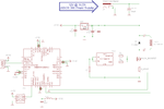
I am designing a inductor saturation test device, which looks like this:

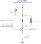
but to simplyfie here is the basic circuit:

I have some question marks that I have failed to find answers to my self and I can't even order parts before some of them are answered, anyway here they are:
1, I have previously in hast soldered together a device such as this before(using the same 12V@16,5A as this) only without the mcu and using my function generator to control the MOSFET gate but I consider that a failure since the current couldn't saturate a T106 size toroid made out of material 26(yellow/with iron powder core used in ATX supplies), and I want to use the 12V @ 16,5A supply this time around as well and as I understand it I can increase the peak current by increasing the bulk capacitor and maybe increasing the delay between pulses to the MOSFET gate.
Is that correct?
2, I have tried my best to grasp the content found online about capacitor equations but I don't get if it is possible to calculate how high a current I can draw from a fully charged capacitor of x µF(at 12V) which is then discharged during a activation of the MOSFET in the above circuit that lasts for n µSeconds?
3, if the voltage to be switched is 12V how high Drain to Source Voltage(Vds) do I need and does the fact that the MOSFET is going to switch a heavily inductive load influence the Vds needed?
4, my application does not utilize a continues current so that parameter from a MOSFET datasheet is unrelevant, but the pulse peak current is defined over a time duration that isn't even close to that of which I will be sing and it also is defined for 1% duty cycle.
How do I relate a peak current in my design to the rated current of a MOSFET?
I am very uncertain about how high a current I should aim for and how to design the circuit to be able to deliver that, I will probably not need the peak current often but I need to be able to saturate cores with high currents at rare occasions.
It would be a big inconvenience for me if I can't use the 12V @ 16,5A supply
About the current peak, is occurs to me that it should be limited by the inductor series resistance... But I guess that the power supply have some fancy current limiting mode, but a big cap should allow for higher pulsed current peak...
Regards
- - - Updated - - -
I should say since I do from time to time attend this forum frequently that I am not as lucid as I use to be(not that I was particularly lucid before), I am in the process of finding a ADD medication that works and my ability to think and grasp concepts is 100% dependent on my medication. And to not bore you with this subject I can simply say that I am now and for a the coming month on a med that isn't close to good enough. Which result in a direct effect on how confused and fussy my mind is so I apologise if I will write more confusing stuff than usual.
I am designing a inductor saturation test device, which looks like this:

but to simplyfie here is the basic circuit:

I have some question marks that I have failed to find answers to my self and I can't even order parts before some of them are answered, anyway here they are:
1, I have previously in hast soldered together a device such as this before(using the same 12V@16,5A as this) only without the mcu and using my function generator to control the MOSFET gate but I consider that a failure since the current couldn't saturate a T106 size toroid made out of material 26(yellow/with iron powder core used in ATX supplies), and I want to use the 12V @ 16,5A supply this time around as well and as I understand it I can increase the peak current by increasing the bulk capacitor and maybe increasing the delay between pulses to the MOSFET gate.
Is that correct?
2, I have tried my best to grasp the content found online about capacitor equations but I don't get if it is possible to calculate how high a current I can draw from a fully charged capacitor of x µF(at 12V) which is then discharged during a activation of the MOSFET in the above circuit that lasts for n µSeconds?
3, if the voltage to be switched is 12V how high Drain to Source Voltage(Vds) do I need and does the fact that the MOSFET is going to switch a heavily inductive load influence the Vds needed?
4, my application does not utilize a continues current so that parameter from a MOSFET datasheet is unrelevant, but the pulse peak current is defined over a time duration that isn't even close to that of which I will be sing and it also is defined for 1% duty cycle.
How do I relate a peak current in my design to the rated current of a MOSFET?
I am very uncertain about how high a current I should aim for and how to design the circuit to be able to deliver that, I will probably not need the peak current often but I need to be able to saturate cores with high currents at rare occasions.
It would be a big inconvenience for me if I can't use the 12V @ 16,5A supply
About the current peak, is occurs to me that it should be limited by the inductor series resistance... But I guess that the power supply have some fancy current limiting mode, but a big cap should allow for higher pulsed current peak...
Regards
- - - Updated - - -
I should say since I do from time to time attend this forum frequently that I am not as lucid as I use to be(not that I was particularly lucid before), I am in the process of finding a ADD medication that works and my ability to think and grasp concepts is 100% dependent on my medication. And to not bore you with this subject I can simply say that I am now and for a the coming month on a med that isn't close to good enough. Which result in a direct effect on how confused and fussy my mind is so I apologise if I will write more confusing stuff than usual.


