Continue to Site

Welcome to EDAboard.com

Welcome to our site! EDAboard.com is an international Electronics Discussion Forum focused on EDA software, circuits, schematics, books, theory, papers, asic, pld, 8051, DSP, Network, RF, Analog Design, PCB, Service Manuals... and a whole lot more! To participate you need to register. Registration is free. Click here to register now.

Arc vs 45-degree PCB Routing

Status
Not open for further replies.

Politecnico

Member level 1
Member level 1
Joined
Aug 28, 2013
Messages
34
Helped
1
Reputation
2
Reaction score
1
Trophy points
8
Activity points
316
Hello everybody

Although my question may seem to be trivial, I'm still looking for a convincing answer!

Regarding PCB routing, at the time of right-turn, we have the options of 45-degree routing as well as Arc routing. While I have read many reviews that Arc is much more reliable, still many professional boards (like the attached PCB made by Texas Instruments) use the 45-degree method.
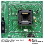
MSP430.jpg

Could anyone help me understand about the advantages and disadvantages of both methods?

Thanks a lot!
 

45 degree routing is optimal when you have space constraints. You can pack more tacks in the same space. If you have space, use arcs. Arcs radiate less signal compared to the 90 degree or 45 degree tracks. For small signals, the difference may not be much but for power RF, ARC is the choice. Any sharp bend will cause some radiation at RF signals and these signals may be picked up by other tracks.
 

Don't make any difference, right angles, 45 degree or arc... no difference until you get into low GHz... And no they do not cause radiation, how are they going to radiate from the corners, electrons crowding round the bend maybe...LOL
Suggest you look up some of the stuff by Henry Ott, Ralph Morrsion and Howard Johnson, plus look in the PCB section we have discussed this before many times.....

The design shown is not RF and I suspect that we are talking about normal digital signals, RF has more concerns than PCB corners.
 

Here is two documents on 90, 45 and arcs. But remember this is all frequency dependent and i have never seen a document saying at what frequency these corners make a difference.

rohm page 10
TI page 13
 

Attachments

  • Buck pcb layout VERY GOOD Rohm- converter_pcb_layout_appli-e.pdf
    491.4 KB · Views: 371
  • high speed pcb routing ti ok slla284a.pdf
    487 KB · Views: 599

Early in the electronics of the 80s, the use of plotters was very common to draw photolithography for PCB manufacturing, and from the point of view of the algorithm designated to build these corners, using 45 degree angles did not require any processing efforts, once both stepper motors would be moving forward together, whereas to draw an arc would have to perform several algebraic opperations. At least it was the explanation that I got at that occasion when asked the same as you, but sincerely in my oppinion the use of 45 degrees angles tend to reduce problems caused by jagged lines.
 

Thanks marce. The article is setting things straight.
Right-angle bends in PC-board traces perform perfectly well in digital designs in speeds as fast as 2 Gbps. In most digital designs, the right-angle bend is electrically smaller than a rising edge.

If we talk about radiated EMI, it should be mentioned that open transmissions are radiating to some extent anyway. Trace discontinuities are just radiating a bit more. It's pretty usual to do mitered routing, but you shouldn't fancy relevant electrical effects for most designs (except in high GHz). It's more a matter of style. Arc routing is somehow a reference to the good old days of paper tape layouts, but it looks nice and is at least an option for PCB artwork exposed to the user's eyes, e.g. adapters. Or high GHz...
 

https://www.ultracad.com/articles/flying.htm

A humorous look at flying electrons, or radiation from trace corners... If it did happen we would be blasted with X-Rays from every PCB and electrons would have to travel near the speed of light when traveling down a trace or wire when conducting (NOT orbit velocity, that is different).
 

Every conductor having a varying current produces electromagnetic radiation. Sharp corners (smaller radius of curvatures) radiates more energy in comparison. Every time you switch on/off an electric/ magnetic field you produce electromagnetic radiation.

X-rays are produced when high energy electrons are suddenly stopped (Bremsstrahlung) - you can put your AM radio on the top of your laptop or PC and 'listen' to the radiation from all sources...
 

There are some scholarly articles on this that I will try and dig out that show there isn't much difference at the corners... some but very low.
The reference to X-Rays and electrons is in reference to the linked article where an EMC expert claimed electrons fly of the traces at corners, if this was so the electrons would be travelling that fast down the PCB trace that any collisions with other atoms would cause X-Rays to be emitted, as we know electrons don't move very fast when conducting so we don't have to worry when they do collide with other atoms which happens often in conductors....
 

X-rays are produced when high energy electrons are suddenly stopped (Bremsstrahlung) - you can put your AM radio on the top of your laptop or PC and 'listen' to the radiation from all sources...

Wow, you must have a really impressive AM radio if it can pick up radio in the X-ray band. My pitiful excuse for an AM radio tops out at 108 MHz.
 

Wow, you must have a really impressive AM radio if it can pick up radio in the X-ray band. My pitiful excuse for an AM radio tops out at 108 MHz.

You PC does radiate lots of noise and some of them will be picked up by your AM radio (common AM band ends around 30 MHz). What you will actually get is the signal in the band you have tuned to. If you tune to another band you will still hear the noise clearly indicating that the noise is rather 'white' in colour. To get X-rays you will need electron energies greater than 20KeV.

My cheap (chinese) radio cannot even tune well when the PC is on (it is a old desktop) but with the PC off, it works well- rather well on FM. FM signals are rather noise resistant.
 

I was only joking about your x-ray AM radio. ;-)

I also know that PCs are quite noisy for AM radio.
 

Anyway as promised ONE white paper, there are more but if you are interested you may do your own extra research....
https://montrosecompliance.com/wp-content/uploads/2014/09/corners-USA.pdf

Worth looking at as are the others out there (I have a 7.5G collection of this sort of stuff! and no life:)) always question your beliefs they may be misguided as are many PCB based myths.....
 

Status
Not open for further replies.

Part and Inventory Search

Welcome to EDABoard.com

Sponsor

Back
Top