Continue to Site

Welcome to EDAboard.com

Welcome to our site! EDAboard.com is an international Electronics Discussion Forum focused on EDA software, circuits, schematics, books, theory, papers, asic, pld, 8051, DSP, Network, RF, Analog Design, PCB, Service Manuals... and a whole lot more! To participate you need to register. Registration is free. Click here to register now.

logic for transmitting serial data using PIC microcontorller

Status
Not open for further replies.

Arrowspace

Banned
Full Member level 3
Joined
Jan 23, 2015
Messages
186
Helped
3
Reputation
6
Reaction score
3
Trophy points
18
Visit site
Activity points
0
I am trying to send serial data output from single pin using PIC18f4550

what logic I have to implement if I want to send 01001010
using RB0 pin.

My serial port is busy with some other function.

I am using serial to parallel connected at RB0 pin of microcontorller

I have used timer to generate clock, but not getting how to transmit data using single pin.
 

There is already hardware support on the uC to do that using assychronous transmission with UART built in module. Depending on the compiler that you are using, it isalso possible to implement such communication via firmware by API functions available at specific library.
 

There is already hardware support on the uC to do that using assychronous transmission with UART built in module. Depending on the compiler that you are using, it is possible to implement such communication via firmware by API functions available at specific library.

I already told my UART busy with some other work.
 

You could certainly implement a software UART (softUART) with only a TX line, as long as the baud rate remains sufficiently low there shouldn't be any major issues.

What compiler are you currently using?

Of course, another possible option is to utilize a multiplexer in addition to the existing device's hardware UART module, feasibility of this option depends largely on its current task and workload.

I am using serial to parallel connected at RB0 pin of microcontorller


Could you also elaborate on your above statement? What exactly are you implying by the phrase, "using serial to parallel connected.."


BigDog
 

You could certainly implement a software UART (softUART) with only a TX line, as long as the baud rate remains sufficiently low there shouldn't be any major issues.

What compiler are you currently using?

Of course, another possible option is to utilize a multiplexer in addition to the existing device's hardware UART module, feasibility of this option depends largely on its current task and workload.


Could you also elaborate on your above statement? What exactly are you implying by the phrase, "using serial to parallel connected.."


BigDog

I have limited pin on my microcontorller ,that's why I have use serial to parallel converter, connected at RB0 pin , for clock I have use timer, clock is generating fine , I have checked, problem is data. How can I transmit serial data using single pin.

serial to parallel 74HC595
 

Software UART is pretty standard and supported by a number of PIC compilers (e.g. CCS-C, mikro C) with built-in functions. And it's easy enough to write from the scratch if you have basic knowledge of low-level microprocessor programming.

There's howver a different problem with your intended design:

I am using serial to parallel connected at RB0 pin of microcontroller
serial to parallel 74HC595
How? 74HC795 is a simple shift register, not an UART. It needs three signals (serial data, serial clock, latch clock) for a SPI like interface. Apparently you didn't think your design through to the end.

An UART receiver needs a stable time base and additional logic to decode the serial data. UART is unlikely to be the right solution for your problem.

If the additional pins required for a synchronous serial protocol aren't available, you can think about something similar to Maxim/Dallas one-wire protocol. It's a serial protocol coding 0/1 bits by pulse width.

- - - Updated - - -

See below an example circuit that controls a SPI interface (like HC595) through a single wire.
 

Attachments

  • OneWire-SPI.pdf
    37.1 KB · Views: 189

I have limited pin on my microcontorller ,that's why I have use serial to parallel converter, connected at RB0 pin , for clock I have use timer, clock is generating fine , I have checked, problem is data. How can I transmit serial data using single pin.

serial to parallel 74HC595

Unfortunately, at this point this thread is more akin to a game of 20 questions, than an attempt to provide a meaningful solution.

I would suggest taking a step back and describing exactly what is the overall intend task.

For example, what is at the receiving end of this data you are attempting to transmit? Another microcontroller? A device with a UART interface?

Or are you attempting to control various devices from the parallel output of the 74HC795?

As FvM suggested 1-wire interface maybe a possible solution, but only if an appropriate device is at the receiving end, like another microcontroller.

However, as your description of the task and issues you face are vague, we are only guessing at this point.

So please elaborate on the specifics of your design and the required task, so that we may assist you.


BigDog
 

More information would be useful but I'm getting the impression Arrowspace is using the shift register as a port expander rather than a UART so the start/stop bits are not needed. If that's the case, another pin is needed to clock the shift register or else some other scheme is needed to derive a clock from the data level changes. The method for actually shifting a byte out bit-by-bit is simple, just shift it in software and depending on whether you send it MSB first or LSB first, test the MSB or LSB and copy it to the pin.
We need to know the assembler or compiler you are using to show an example.

Brian.
 

Hi,

use a software UART.
It needs only one pin (per direction), no external component. No HC595.

Simple and proved.

Klaus
 

What are you trying to do ? Do you want to sent integer value or character ? What is connected to the output of HC595 ? LEDs? If you want to send data to Serial to Parallel Shift register then you need 3 wires to interface it to MCU. You have to write software SPI function which sends out 8 bits of data with MSB first and then after you clock 8 bits of data using CLK and Data pins then you have to send one pulse to ST_CP pin of HC595 and this will store the serial data at the parallel output.
 

Ok. It is very simple. You are controlling Relays. You need 3 pin of MCU to interface 74HC595. Alternatly you can use I2C or SPI port expanders like PCF8574T which needs I2C or SPI module in your MCU. If you need low cost then use 74HC595. What is the problem ? Don't you have 3 MCU pins to connect 74HC595 to it ?
 

Hi,

all you need is to talk to this HC595?

It comes into my mind, that you don´t need UART at all.

You need SPI to talk to HC595.
Can you use PIC hardware SPI?, Or look for "SPI bit bang mode" or "software SPI".

Klaus
 

- - - Updated - - -

Ok. It is very simple. You are controlling Relays. You need 3 pin of MCU to interface 74HC595. Alternatly you can use I2C or SPI port expanders like PCF8574T which needs I2C or SPI module in your MCU. If you need low cost then use 74HC595. What is the problem ? Don't you have 3 MCU pins to connect 74HC595 to it ?


Ya right I have only 2 pin in my microcontroller , I have posted my circuit , is that correct ?


Please find my circuit to get better understanding , I already told my serial port is busy and I do't you sufficient pin at my microcontorller that's you I have used serial to parallel communication IC 74HC595.
You have "already told" some things, but they didn't make much sense yet.

Now you are presenting a HC595 circuit that uses two pins rather than one processor pin. But it's still a bad design because it latches wrong data during the shift. Can be possibly tolerated for relays control because relays are slow.

If this solution works for your, we can close the discussion. Otherwise you can refer to the suggestions that have been already made, e.g. the one-wire logic.

- - - Updated - - -

See if methods used in these projects can be used for your purpose.
The first one is only working specifically with LCD interfaces, the second one should work, it's doing something quite similar to my post #7, applying some simplifications that are possible with HC595.

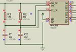
ow.png

Strictly speaking, the RC lowpasses are violating the HC595 input rise time specification, but I guess the design will work though.
 

You have "already told" some things, but they didn't make much sense yet.

Now you are presenting a HC595 circuit that uses two pins rather than one processor pin. But it's still a bad design because it latches wrong data during the shift. Can be possibly tolerated for relays control because relays are slow.

If this solution works for your, we can close the discussion. Otherwise you can refer to the suggestions that have been already made, e.g. the one-wire logic.

- - - Updated - - -


The first one is only working specifically with LCD interfaces, the second one should work, it's doing something quite similar to my post #7, applying some simplifications that are possible with HC595.

View attachment 120703

Strictly speaking, the RC lowpasses are violating the HC595 input rise time specification, but I guess the design will work though.

from where you sending data on DS Pin

- - - Updated - - -

See if methods used in these projects can be used for your purpose.

http://www.libstock.com/projects/view/660/2-wire-serial-lcd-using-cd4094

http://www.libstock.com/projects/view/1430/one-wire-16x2-20x2-20x4-lcd

I think the One-Wire LCD method will be fine. It uses one pin to interface 74HC595 to MCU. Timings are critical.

Your circuit is wrong. You cannot tie SH_CP and ST_CP. This way for evry bit data sent to 74HC595 it will immediately appear at the output.

but I am not getting any output .
 

Copy and paste the One Wite LCD circuit and make changes to it. Don't use REALCAP model in proteus for simulations. It doesn't work. I have tested it. Atleast it did not work with the One Wire LCD circuit. Neatly draw your circuit in Proteus (using one wire circuit) and post it here. I will write the code for you. Do you get Relay Data from UART and assigning the processed data to 74HC595 ? If yes, from UART do you send ascii char or integer value ? Which compiler are you using.

from where you sending data on DS Pin

Based on how long the 1's and 0's remain the capacitors charge and provide the DS and ST_CP signals.

Remember the timing in the code of One Wire circuit is critical. If your compiler's delay_us() and delay_ms() functions doesn't generate proper delays then it will not work.
 
Last edited:

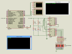
Here is the circuit I made. I wrote the code in mikroC Compiler. Which Compiler are you using ?

broken link removed
 

Attachments

  • Relay Control.png
    Relay Control.png
    70.7 KB · Views: 204
Last edited by a moderator:

Status
Not open for further replies.

Similar threads

Part and Inventory Search

Welcome to EDABoard.com

Sponsor

Back
Top