Continue to Site

Welcome to EDAboard.com

Welcome to our site! EDAboard.com is an international Electronics Discussion Forum focused on EDA software, circuits, schematics, books, theory, papers, asic, pld, 8051, DSP, Network, RF, Analog Design, PCB, Service Manuals... and a whole lot more! To participate you need to register. Registration is free. Click here to register now.

[SOLVED] UART Read Error with PIC microcontrollers and SIM300 GSM module

Status
Not open for further replies.

Mithun_K_Das

Advanced Member level 3
Joined
Apr 24, 2010
Messages
899
Helped
24
Reputation
48
Reaction score
26
Trophy points
1,318
Location
Dhaka, Bangladesh, Bangladesh
Activity points
8,254
As the micro-controller works in 5V and the SIM300 GSM module works in 3.7V to 4.2V while the Tx of SIM300 is less than 3.3V as the datasheet says.
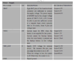
1.PNG
2.PNG

datasheet: included with this post as attachment.


I used PIC and SIM300 module to send SMS many times and it works clearly. But only problem is in reading any data. Is this due to the voltage level error? I mean the SIM is sending data at 3.3V range and the PIC is reading data at 5V range. Will it create any problem in data reading?

What I found in reading data with micro-controller is, it frequently miss characters and sometimes reads noise or blank. Although the simulation works fine and clear, no missing in data. That means that the program works fine. Only problem is in my hardware.

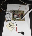
Here is the hardware I used in Data reading from SIM300cz with PIC micro-controller:

I didn't draw any schematic diagram, but I've the PCB layout.
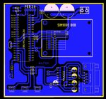
Capture.JPG

Also, A similar post was posted before.
Link: https://www.edaboard.com/threads/330732/

Today I found a project related with SMS reading from SIM module using micro-controller. They are using MAX232 in between the micro-controller and SIM module. Here is the link and their circuit diagram:
Wireless-Electronic-Notice-Board-using-GSM-Circuit-Diagram.jpg
link: https://www.electronicshub.org/wire...onic_Notice_Board_using_GSM_Circuit_Principle

Is it ok to use MAX232 in this way or will it be harmful to the SIM module/GSM module?

Or it will work fine? As the voltage level error is solved...
 

Attachments

  • SIM300.PDF
    2.7 MB · Views: 119
Last edited:

I suspect the MAX232 circuit drives a module with an RS232 interface. The SIM300 needs a direct connection and would likely suffer damage if driven at the high voltages the MAX232 produces.

Most PIC devices when running on 5V supply have a high input threshold of 2V so data from the module should work fine. When driving the module you should limit the data high level to no more than the module's VDD level. You can do that easily with a potential divider.

Brian.
 

I think max232 rx/tx and pic rx/tx tied together with jumpers on the given link. RS232 standard is point to point(beetwen two units). Two tx signal on one wire. This possible caused garbled or missing bytes. For the max232 you can use a second(soft)UART on not connected IO pins.

(sorry for my english)

Joc
 

Yes. But according to SIM300 datasheet, the Tx terminal voltage is,

V_EXT (3.0V)X0.7 = 2.1V on an average.
V_EXT (3.15V)X0.7 = 2.205V maximum. &
V_EXT (2.85V)X0.7 = 1.995V minimum.

So its pretty low for PIC I think. Should I use any other Opto-coupler or voltage level shifting circuit or buffer?
 

pic16f887 has wide operating voltage range 2.0 to 5.5 Volts.
The pcb works with any terminal without pic16?
 

The appropriate interface type and signal levels depend largely on the specific breakout board or module you plan on incorporating into your design. While you have posted the datasheet for the base SIM300 module, you have not provided the datasheet/schematics for the SIM908C BOB you have specified on your PCB silkscreen. Without the particulars of that specific BOB, accurate meaningful advice cannot be provided.

The interface is most likely asynchronous serial (UART), however it's unclear as to whether the interface is TTL or RS-232 levels. An incorrect guess would most likely damage either the microcontroller or the SIM300 module, therefore it would be prudent to provide specifics, i.e., schematic, datasheet, etc., before design finalization or hardware implementation.


BigDog
 

Yes, but both are same. maybe The name is written as SIM908BOB but its same to SIM300Cz. Same pin configuration in that BOB with two different types of SIM module.

I'm not sure what type of voltage level it is, TTL/RS-232. But its Asynchronous UART communication.
 

Yes, but both are same. maybe The name is written as SIM908BOB but its same to SIM300Cz. Same pin configuration in that BOB with two different types of SIM module.

Highly doubtful, as per the SIM300 datasheet, the SIM300 base module has a 60-pin connector carrying a wide variety of signal lines, while the connector of SIM908C BOB you have incorporated into your design has only an 8-pin connector.

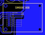
SIM908C BOB Connector
SIM908CConnector.JPG

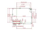
SIM300 Base Module Connector
SIM300Connector.JPG

Therefore, it was up to the designer of the specific BOB as to how the handled the particular signal lines they decided to breakout. It could be TTL, may have an RS-232 transceiver onboard, or some other way of handling those particular signal lines.


BigDog
 

I think, you should think twitch before you write or say something. I've already posted a link and if you visit that link you'll find an image of this type of Break Out Board.

First see that image then make some comments. Although you are an administrator, but you really really talk/comment about unexpected topics those are not related with the main issue.

The problem is not how the BOB looks like, the problem is with the technological issue. I think you understand now.

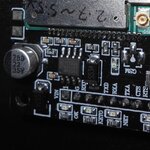
Here is the image:
DSCN1212.JPG

I've similar Break Out Board or so called complete module of SIM300cz with similar to this one. Same pin configuration and same look like.
 

I think, you should think twitch before you write or say something. I've already posted a link and if you visit that link you'll find an image of this type of Break Out Board.

Perhaps, you should heed your own advice, an image is NOT a datasheet or schematic.

You have neither mentioned the specific make and model of the SIM300 BOB you currently have nor provided its datasheet or schematic in neither this thread nor the following thread, both of which I have examined thoroughly.

https://www.edaboard.com/threads/330732/

Where is the datasheet or schematic for your specific BOB?


First see that image then make some comments. Although you are an administrator, but you really really talk/comment about unexpected topics those are not related with the main issue.

The problem is not how the BOB looks like, the problem is with the technological issue. I think you understand now.

EXACTLY MY POINT!

As you just pointed out, a vague image of a similar looking BOB is largely irrelevant. The issue here is the actual design of YOUR BOB, i.e., the datasheet or schematics of YOUR BOB, which would indicate how exactly the TX/RX and other lines are handled, i.e., whether or not there is a RS-232 transceiver incorporated into the BOB. The datasheet of the SIM300 base module cannot convey this vital information.

How could it, as the SIM300 base module is only incorporated into the design of another manufacturer's BOB.


Here is the image:
View attachment 120229

I've similar Break Out Board or so called complete module of SIM300cz with similar to this one. Same pin configuration and same look like.

Irrelevant!

You will need to post the datasheet and/or schematics of your specific BOB. Barring that, you'll need to analyze/measure the signals emanating from the relevant pins and/or examine the BOB for any any additional relevant devices, i.e., RS-232 transceiver.

Get a grip.

BigDog
 

Firstly, it's a SIM908 not a SIM300 but they are electrically very similar. The interface is MOS, not TTL or RS232 although natively the module is closest to TTL. If you download the hardware data sheet for the module it shows several circuits for interfacing to and from the module to 3.3V and 5V external circuits. I suspect the small IC on the BOB is the 4V supply regulator but please tell us it's part number in case it's a serial level shifter.

Brian.
 
Firstly, it's a SIM908 not a SIM300 but they are electrically very similar.

Unfortunately, that is not entirely clear, the thread title and the upload datasheet indicates it is a SIM300, as does Mithun_K_Das indicate it is a SIM300cz in post #1 and #7, while the previous thread title and posted content refer only to the SIM908, the SIM300 is never mentioned.

In any event, as we've now both pointed out, the real issue is whether or not any RS-232 transceiver or level shifting has been performed on the BOB itself.

Also, as Mithun_K_Das indicated, the posted images of the BOB only look similar and are actually not the BOB in question.

Posting the datasheet or schematic of the actual BOB would certainly alleviate any doubts at this point.


BigDog
 

Obviously, thats the 4V regulator for the SIM908 module so we can ignore it from the communications aspect.

The logic high voltage for the SIM300 module is quoted as minimum "EXT_VDD - 0.2V" so it should be OK to connect directly to a 5V PIC USART input but you need to drop the voltage from 5V to ~3V from PIC to module. I'm currently working on a unit with SIM800 modules and that specifies a minimum VOH on the UART of 2.1V so if you take that as a worst case example, it should still be readable by the PIC, albeit with limited noise immunity.

Brian.
 
I tried connecting Tx of SIM300/SIM908 directly to PIC Rx, it reads noise or blank space.

But if I connect them using two MAX232 back to back, it is little bit noise free and less blank space. But if I simulate the code in Proteus, it can read all the data clearly. That means code is working fine.

This is why I'm confused, if the voltage level is creating any problem reading data from SIM module.

I used these two module many times before to send SMS only. Each time it works fine without any error. Although I connected PIC Tx directly to SIM Rx. It did not make any damage to SIM module. I think I should use a voltage divider at least. So I'm keeping this in mind in next design.


But, the problem is when I try to read any data from SIM module. Error comes. I checked the same circuit connecting with PC COM port. It can read everything clearly. This is why I'm confused about voltage level or something other issue related only with SIM module.

any way, thanks Brian for your some valuable words.
 

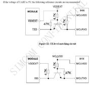
This is what Simcom recommend:


Brian.
 
Many many thanks Brian, Now I'm getting almost no error or noise while reading any UART from SIM modules. I tried with SIM300cz and SIM908C. I'm getting clean texts from UART read. No error or noise or space.

Screenshot_2015-08-25-11-53-23.png

Here is the screen shot of my last GPS Response after reading UART via SMS.
 

Status
Not open for further replies.

Similar threads

Part and Inventory Search

Welcome to EDABoard.com

Sponsor

Back
Top