Continue to Site

Welcome to EDAboard.com

Welcome to our site! EDAboard.com is an international Electronics Discussion Forum focused on EDA software, circuits, schematics, books, theory, papers, asic, pld, 8051, DSP, Network, RF, Analog Design, PCB, Service Manuals... and a whole lot more! To participate you need to register. Registration is free. Click here to register now.

[SOLVED] Problem with an old 10KV/3mA DC high voltage module

Status
Not open for further replies.

agoo

Member level 3
Member level 3
Joined
Sep 28, 2013
Messages
55
Helped
0
Reputation
0
Reaction score
0
Trophy points
1,286
Visit site
Activity points
1,734
Hello all

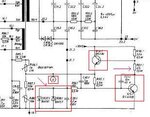
I am using an old 10KV/3MA DC high voltage module and a few times I repaired it because parts are very old but this time I have stuck. When I don't connect any load (usually about 3.3 mega ohm 1.5W passive resistors) I have 10 KV at the output but when I connect the load, high voltage get killed. There is a pin (0-10V) shows what KV I have at the output. With no load I have 10V there but with load I only have 2V. I used to have 10V with load. I need help to diagnose and find the problem. Those who are familiar with HV circuits please advice. Schematic is attached.

Agoo
 

Attachments

  • HV.JPG
    HV.JPG
    114.6 KB · Views: 219

I have measured voltage and current at point 13.1 at the primary of the high voltage transformer. With no load I have got about 70V and 400 mA which is normal but with 3.3M load I have got 42V and about 200 mA current at this point. Also there seems to be no current overload since in case of current overload HV turns off. Also Q12.1 and Q13.1 are both OK. With this information please advice what might be the problem or what to do to get close to the problem?
 

It's a self oscillating HV generator, all the circuitry to the left of CR291 is power supply or monitoring. It obviously is oscillating or you wouldn't get any HV at all so I would concentrate your attention around the chain of resistors and capacitors between the transformer and 10KV output. Quite likely one of the resistors has gone high in value or open circuit.

Brian.
 

Brian

All the chain of resistors and capacitors between the transformer and 10KV output are located on a separate board which luckily we had a working spare one. I replaced it but no use and still problem is there.

Agoo
 

Brian

I think drop of the voltage from about 70V to 42V and current from 400 mA to 200mA at the primery of the HV transformer is a clue. As I said before when I have no load there is about 70V/400mA at the primary but when I connect the load this drops to about 42V/200mA which is odd. I guess wrong feedback from output somehow pulls down the voltage and current at the primary causing HV drop. What do you think for the next step?

Agoo
 

It is always difficult to predict what a fault in the output stage would do because of it's self oscillating nature. By substitution you have eliminated most of the HV circuits so it was a worthwhile exercise.

Assuming the incoming supplies are stable, I think the next step is to break the feedback loop. The voltage at point 'P' appears to be correct as it is used to derive the 10V at the monitoring port so the fault is to the left side of that. Before going further though, can you show where the two lines at the bottom of the diagram connect to please. I refer to the one from the output of IC9 and the one above it.

Brian.
 

It seems this two lines are also for monitoring purposes. I have attached the other part. Have a look and let me know what do you think?

- - - Updated - - -

It seems this two lines are also for monitoring purposes. I have attached the other part. Have a look and let me know what do you think?
 

Attachments

  • hv.JPG
    hv.JPG
    99.5 KB · Views: 175

Brian

Just as a reminder regarding point "P" when there is no load monitoring 10V is there but when load is connected this 10V drops to about 2 V.

Agoo
 

I'm assumed from the 'P' voltage reflecting the actual output voltage that the circuit around IC8 was working correctly.

This is one of thse situations where it could probably be fixed in five minutes on my workbench but diagnosis by internet could take a long time.

Q1. Can you tell me what voltage is at Uref, (point M) on the diagram and see if it stays constant when you apply and remove the HV load.
Q2. Can you tell me the voltage at each end of R49 (input current compenstion pot) and again see if it changes when the load is applied.

Brian.
 

Brian

1- Voltage at point M (Uref) is 10V with or without load (no change)

2- Voltages of R49: at top (to Q10 collector) is 12.2 V, bottom (to Q11 collector) is 7.6V and midlle point of R49 is 10.6V and there are no changes in these voltages with or without load.

One thing I notices is at point "K" I have 4.6V with no load and 14V with load which is a huge difference.
Also I noticed pin 2 of IC5 drops from 10V to 4.6 when I connect the load.
Most important is voltage at point "j" which is 0.5V with load and -5.0V without load?
Also I noticed pin3 of IC5 drops to 6.2V from 10V when I connect the load.
Does these give you any clue?

Agoo
 
Last edited:

1. That's good, I was checking the reference voltage was present and stable.
2. Also good, if these had been wrong the error amplifier IC5 wouldn't work properly.

Point "K" is saying "I need more voltage" so it is good that it increases as you apply the load. I suspect you should not normally see such a big change when it is working properly.

I would not expect IC5 pin 3 to change much when the load is connected. It is only fed from Uref which you have confirmed is constant. There may be some current changes inside IC5 causing it so I treat it with suspicion rather than condemning it.

What definitely seems wrong is the voltage at point "J", if it goes negative it stops Q9 from regulating the main power line. It could be doing this as an over-reaction to the power line voltage being wrong though. It's always difficult to work with circuits like this where a fault anywhere in a loop makes all the voltages within the loop wrong. It's almost impossible to see what is cause and what is effect.

Some more tests please, again with and without load applied:
What are the voltages at the pins of Q9 and the five transistors directly above it. Sorry, I can't read their part numbers on the diagram.

Brian.
 

Hello Brian

Voltage at base of Q16 is 90V both with and without load.
Voltage at base of Q9 is -4V no load and 350 mV with load.
Voltage at Collector of Q9 is 90V with load and 89V without load.
Voltage at base of Q8 is 90V no load and 91V with load.
Voltage at collector of Q25,Q7,Q6 and emitter of Q8 (all connected together) is 91V with load and 90V without load.
Voltage at collector Q9 (connected to base of Q25) is 75V with load and 41V no load.
Voltage at emitter of Q25 (connected to base of Q7 and Q6) is 74V with load and 41V without load.
Voltage at emitter of Q7 and emitter of Q6 both are 74V with load and 40V without load.
Voltage of point "G" is 42V without load and 73V with load.

Any clue?

Agoo

- - - Updated - - -

Brian

I measured a few points on a borrowed similar HV unit. Results are as follows:

Voltage at point "J" is 0.5V with and without load.
Voltage at point "K" is 4V with load and 6V without load.
Voltage at collector of Q9 ia about 90V with and without load.
Voltage at Q9 base is 0.5V with and without load.

I hope this gives you a real good clue.
 

Now I'm really confused!

In post #2 you stated the voltage at transformer 13.1 is 70V and it drops to 42V under load.
In post #12 you say point "G" is 42V without load and it increases to 73V under load.

They are connected together so either there is a break close to point "G" or you have the voltages mixed up.

Brian.
 

Brian

Sorry as you said I have got voltages mixed up in post #2. Correct measurment for pint "G" is about 42V without load and about 70V with load.

Agoo
 

OK, it seems the incoming supply is fine but something in the 6 transistors at the left of the schematic is both limiting the available current and also failing to respond to the feedback voltage from IC4.

My diagnosis (for now!) is a faulty Q9. My reasoning is:

When more current flows through Q9 it should increase the voltage to the transformer. Point "J" is responding sensibly because it's voltage increases with demand on the output when a load is applied although the voltage is a little low. With load, "J" rises to 0.5V but the other side of R38 only has 0.35V on it which implies base current is flowing, despite it being below the turn on voltage of the B-E junction. Q9 collector voltage appears to be following the failed supply voltage rather than controlling it.

Do you have a replacement BF257 you can substitute? The type isn't critical as long as it has a VCEo of >100V.

Brian.
 

Brian

Yes I had a spare BF257. I replaced it but no use. Problem is still there. I also replaced Q8.1 with a spare one I had and checked C13, C23.1, R33.1 and R37 all are OK too.

Agoo
 

This is frustrating! I need my hands on it to do tests!

Please try this:

Carefully mark the position of the wiper on R41 (or accurately measure the voltage on IC4 pin 2 so you can restore the setting afterwards) then adjust it and see if the voltage at point 'G' changes. Let me know if it does but please return the control to it's original position so we don't start chasing another problem !

Brian.
 

Brian,

After marking R41 I start adjusting it. Voltage of point "G" changes from 68V to 78V when I adjust R41 with load connected but with no load there is no change at point "G" voltage. It stays at about 40V. At the end I returned R41 to its previous position.

Cheers
Agoo
 

Hi agoo!
Protect.JPG
Check the circuit protection. The voltage at the point "U" with the actual load and no load. Base and collector voltage Q13.7 with connected load and no load. With normal load Q13.7 should be closed.
 

That was going to be my next 'best guess', the protection circuit is shutting the HV down prematurely but that wouldn't account for the supply line dropping as the load increases. The protection circuit drains the bias from the HV oscillator which would tend to reduce it's current consumption so there would be less load on the supply. I would anticipate the supply voltage rising to compensate for the extra load until the oscillator was shut down, the opposite seems to be happening. Besides, if the protection circuit operated, I would expect the overload monitor (lamp/LED?) to indicate a fault.

Agoo, try this:
MOMENTARILY short out the base and emitter of Q15 and see how it changes operation. Do not leave it running for long with the short in place as it could overload the HV oscillator transistors. I think it's Q15, the schematic is too blurred to be sure but it's the one in the extreme bottom right corner of the HV.jpg image you posted.

Brian.
 

Status
Not open for further replies.

Part and Inventory Search

Welcome to EDABoard.com

Sponsor

Back
Top