Continue to Site

Welcome to EDAboard.com

Welcome to our site! EDAboard.com is an international Electronics Discussion Forum focused on EDA software, circuits, schematics, books, theory, papers, asic, pld, 8051, DSP, Network, RF, Analog Design, PCB, Service Manuals... and a whole lot more! To participate you need to register. Registration is free. Click here to register now.

[Moved]: Use of Hold time in Sequential Design

Status
Not open for further replies.
Who told you is doesn't? It does.

Just think.

If you've got a hold time of 10nS, you certainly can't run any faster than 100MHz (1/10nS), right?
 

I think barry's example is a bit extreme. I agree logically sunidrak's statement is not precise. but in general, hold time won't be longer than 1ns for current technology of 40n or smaller.
Also, it is usually the setup time as bottle neck of how fast a design can go. Synopsys document regards hold time as a single flop-based concept, not multi-flops based as setup time is. Therefore, my understanding is, single-flop based hold-time is not going to beat multi-flop based setup-time in term of constraint scale.
 

I beg to differ. The statement was "maximum frequency of operation of Sequential design doesn't depend upon Hold time". That is just absolutely wrong. I just used 10nS as an example. If it's 1ns, then your frequency is STILL limited (1GHz.)
 

I agree with your 1ns => 1GHz limit claim. I was trying to say that it is usually the combinational clouds between flops that affect the fastest possible frequency a digital design can run at, not usually the hold time.

I beg to differ. The statement was "maximum frequency of operation of Sequential design doesn't depend upon Hold time". That is just absolutely wrong. I just used 10nS as an example. If it's 1ns, then your frequency is STILL limited (1GHz.)
 

By the definition of hold time, it has nothing to do with period of the clock. Data launch on one edge of clock in launching flop should not change on capturing flop before the same edge of clock is reached in capturing flop. Since, it is the same edge how does the maximum frequency of operation of sequential design depend upon hold time?
 

By the definition of hold time, it has nothing to do with period of the clock. Data launch on one edge of clock in launching flop should not change on capturing flop before the same edge of clock is reached in capturing flop. Since, it is the same edge how does the maximum frequency of operation of sequential design depend upon hold time?

You are talking about a single event, not a complete design. Your "launch" ff cannot get new data until after the hold time has elapsed and THAT limits the system frequency.
 

Sometimes, hold time can be negative depending on the clock skew and data path delay in a given technology node. In that case how would you link "maximum frequency to hold time"?
 

Sometimes, hold time can be negative depending on the clock skew and data path delay in a given technology node. In that case how would you link "maximum frequency to hold time"?

You are being quite stubborn about this. In devices with negative(or zero) hold time, which is common in FPGAs, the manufacturer inserts a delay such that the intrinsic hold time of the flip-flop is moved 'backwards' and added to the setup time. For example, a ff might have a hold time of 5ns and a setup time of 10ns. The manufacturer can change things so that the hold time is zero and the setup time is 15ns.

You can't change the laws of physics.
 

How about some pictures and the timing involved to make things clearer as to how hold time can affect the maximum frequency.

I'll present two cases of a pair of registers clocked with an ideal clock source that has no skew (not realistic, but makes things easier to understand) and the resulting maximum frequency obtainable. I'm also disregarding the effects of PVT on all of this for simplicity sake.

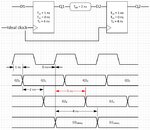
Case1: FFs with 1 ns clock to out, 0 ns setup, and 4 ns hold
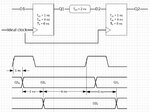
Case2: FFs with 1 ns clock to out, 4 ns setup, and 0 ns hold

Case1:
Capture1.JPG
Maximum frequency is 250 MHz, but this would be very difficult to achieve as there has to be >= 4 ns of hold time, which makes the requirements for the Tco+Tpd have a worst case minimum of 4 ns. Even though the setup time is 0 ns you can't run the clock at 333 MHz due to there not being enough hold time in the Tco+Tpd of 3 ns.
In this case the maximum frequency is defined by the hold time.

Case2:
Capture2.JPG
Now we switch to only setup time with no hold time and the picture changes dramatically as now the requirement becomes Tco+Tpd+Tsu which now requires the clock period be 7 ns. All the extra hold time past 0 ns does nothing to define the maximum frequency.

If you consider that the Tsu-Th window is where the FF doesn't like to see a change in the data relative to the clock. It definitely helps to have more hold time than setup time, if and only if you can guarantee precise timing between the source FF and the destination FF (remember hold time is a minimum value, you have to exceed that value to make sure it meets timing). If you have large variations in minimum and maximum timing (which is pretty much the case), then having small setup times and large hold time really just makes the timing appear more difficult. If instead you have large setup times and 0 hold times then your Fmax goes way down, but it sure is a lot easier to "see" that you've met timing without the though that has to go into thinking about optimizing the hold time and the path delays (I actually think you'll pretty much end up with a nearly identical Fmax anyways due to the minimum to maximum timing variation).

In summary, both hold time and setup time can define maximum frequency, depending on which one is "bigger". I really think it's easier to for tools to analyze setup time and optimize for that delay as opposed to starting with hold time optimization followed by checking the setup time. In the first instance starting with setup time then fixing hold time only requires fixing those paths that may not have enough path delay between registers to meet the hold time requirement of the destination register. Adding delay in that case won't affect setup time. I suspect because of this (ease of hold time timing closure) FFs are designed to have Tsu > Th and Th is typically much closer to 0 ns (positive or negative), and/or I could be completely wrong about this. :)
 
Status
Not open for further replies.

Part and Inventory Search

Welcome to EDABoard.com

Sponsor

Back
Top