Continue to Site

Welcome to EDAboard.com

Welcome to our site! EDAboard.com is an international Electronics Discussion Forum focused on EDA software, circuits, schematics, books, theory, papers, asic, pld, 8051, DSP, Network, RF, Analog Design, PCB, Service Manuals... and a whole lot more! To participate you need to register. Registration is free. Click here to register now.

[SOLVED] Modefying a USB-RS-232 dongle

Status
Not open for further replies.

David_

Advanced Member level 2
Joined
Dec 6, 2013
Messages
573
Helped
8
Reputation
16
Reaction score
8
Trophy points
1,308
Location
Sweden
Activity points
12,236
Hello.

I've bought a USB-Serial/RS-232 converter, not a cheap one of ebay but a real unit with:
Asynchronous Serial Protocol: RS-232
TD, RD, DCD, DTR, GND, SDR, RTS, CTS, RI
Data Rate: Up to 460.8 Kbps
USB: 12Mbits

And I wanted to use this to communicate with my micrcontrollers and I have a few MAX232 ICs, so I thought to solder one of those to a little board with a DB9 female connector.

But when I came to the issue of supplying MAX232 with +5V I turned to opening up the dongle to see if I could get the USBs 5V supply out in a simple way.
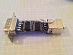
bild 6.jpg

But when I opened it I saw that the converter utilizes a FT232RL together with a SP3243EUEA.
SP3243 is a High Speed Intelligent +3.0V to +5.5V RS-232 Transceivers, and FT232RL is a USB UART IC.

And seeing as I know that FT232RL is a common solution for people to connect to µC's through USB I thought "do I really need MAX232?", but I don't know and I can't as of jet figure out the function of SP3243.

I will draw up a schematic and post asap but I figured I could ask you folks in the mean time.

The dongle outputs around 5,5 to 5,9V according to documents.

Regards
 

Hi,

You bought a USB-RS232 converter and you got one.

RS232 levels are specified to be at least +/-9V. If you don´t need this levels don´t buy a RS232.

Instead you can look for "CMOS level" or "TTL level".
There are boards to buy with FT232 but without RS232 level converters. This is what you need to communicate with a ucontroller.

***********
Look for "USB to TTL Serial cable 5V Converter Adapter" at ebay.
or " USB To Serial Adapter Module"
***********

The term "RS232" is often misused in the meaning of "UART"


Klaus
 
I know I bought a USB-RS232, that's why I bought it;)

But beside the RS232 use of it I also want to talk to micros and thought rather than to buy another converter I could use this + a MAX232, that is straight forward but when I saw FT232RL I thought maybe I don't need MAX232.

I don't want to permanently re-build my RS232 dongle since it is used as such but look at this schematic:
USB-RS232.png

Could I not highjack RXD, TXD and DTR and pass them to a ATmega TXD, RXD and through a capacitor RESET?

Or would I need to cut of the connections to SP3243...

- - - Updated - - -

I might as well build one of those transistor/resistor/zener serial-TTL converters, know I know how the dongle works anyway.
 

Hi,

I think the best solution is to buy a usb-to-serial converter with TTL/CMOS levels (instead of RS232 levels).
Then you don't need to modify anything.

A simple resistor zener combination won't work, beccause the voltage levels are the other way round.
A RS232 high level = -9V, a low level = +9. The transistor is needed to invert the signal.

But for sure you could modify the existing board by:
* either desolder the RS232 chip and use the signal from/to FT232, or
* add another RS232 chip to connect to the ucontroller.

Klaus
 
  • Like
Reactions: David_

    David_

    Points: 2
    Helpful Answer Positive Rating
I think what you are trying to do is avoid the TTL to RS232 then RS232 to TTL conversion by using the original TTL signals directly. Yes you can do it by connecting straight to the FT232RL so it only does the USB part of the job. I think the SP3243EUEA is basically the equivalent of a MAX3243 (MAX243 but using 3.3V instead of 5V) so all it does is the conversion to RS232 levels.

You might face soldering difficulties as these are small devices but electrically I don't see any reason why it can't be done. Beware that you are dealing with 3.3V logic levels, I'm not sure if the FT232RL is 5V tolerant.

Brian.
 
  • Like
Reactions: David_

    David_

    Points: 2
    Helpful Answer Positive Rating
As a long term solution I will get a real µC programmer/debugger/simulator with JTAG but that will take a while due to $$$, another reason to get communication with a controller is to talk to Matlab and to construct a platform for data converter tests using matlab to analyze data.

For know I'm using arduino Due but I have a rather serious error that result in matlab being unable to connect with any arduino as it should be able with support packages, I've been in contact with technical support at mathworks for a week now but no solution.
So I am about to do it manually, while using arduino there are no problem talking to it through USB as with arduino serial monitor but the next step will use a stand alone µC and then I'm not quite sure.

I did not know about FT232 AND 3,3V but that suits me fine since Due is 3,3V µC.
I just found a USB-Serial converter board from ebay:)
Compleatly forgot I had one...

It has GND, CTS, VCC, TX, RX, DTR.
But what I want is to level shift all signals from the DB9 connector, and route the signals to the µC and manage real handshaking.
There are a suitable IC, MAX3241 that handles all signals but it quite expensive. But I have a bag 2N3904 and think I could use them to do a level shifter circuit, It will take lots more board space but as a prototype its fine.

I have to say that this subject is most confusing since online you find a lot of different information and it seams like the words, RS-232, UART and Serial can sometimes mean the same thing.
My solution will be in some ways ridiculous if one would look at all circuits, USB - FT232RL - SP3243 - MAX3241(or transistors).
But handling full RS-232 from a micro is a really good way for me to learn.

So to sum up.
I will at a later time get a real programmer for µC.
I will use the dongle as it was intended and shift the voltage levels to enable interfacing with arduino Due.
 

I agree there is a lot of confusion over naming. The basic definitions are:

Serial means bits sent in series, one after another. In conventional serial transmission, 8 bits of data are sent with an added start bit and an added stop bit making 10 bits in total. Sometimes, you will come across variations such as 7 data bits and a parity bit instead of the eighth bit.

UART (and USART) are the shift register hardware that converts parallel to serial and serial to parallel so bytes can be sent and received on a single wire respectively. It is responsible for adding the start and stop bits when transmitting and when receiving, detecting them to 'frame' the 8 data bits correctly.

RS232 and all the the other 'RSxxx' are electrical specifications. The RS stands for 'Recommended Specification" and they cover all sorts of things as well as data transmission. RS232 is just one of the common serial specifications, using +12V/-12V for sending zero bits and 1 bits respectively. You will also come across RS422, RS423 and RS485 which also define the voltages and cables used to carry serial data.

Brian.
 
//Edit
My FT232RL have a jumper to choose between 3,3V and 5V, But do that effect the chips logic output voltage?
I'm going through the data sheet but haven't found anything jet and I do not have my scope to check, do you know?
//

Thanks for the clairification.

When dealing with the serial communication, am I restricted to the format 1 start bit, up to 8 bits, 1, 1,5 or 2 stop bits?
Arduino Due contains SAM3X8E, a 32bit flash µC. Is it possible to send a 32bit word as such or is it always going to be 4 bytes each with start/stop bits?
And regarding the stop bits, I know I can choose 1, 1,5 or 2 but is that outside of my choice of 8 data bits, so a transmission can be as many as 11 bits, or is it always 10bit streams?

Does any one know about the subject of 3,3V digital pins and what it takes to make them 5V tolerant, if it was easy one would think that it would be standard to make them as such. Although I do bump in to things that is 3,3V and 5V tolerant I never get to use anything that is 3,3V and 5V tolerant. It would make life so very much easier but I suppose it says by it self that the 5V tolerant inputs cost a bit more to produce.

One other thing, does any one know if there are any difference in speed or performers of serial RS232 communication with real full hardware handshake and pure software handshake, hardware do sound more versatile but is it slower...
It does not really matter to me right know but I can't help wonder about the pros vs cons of hardware/software handshaking, obviously in applications where it is needed as I understand in some or many cases it is not needed at all.

I am looking through matlab since I'm new to it to see if it can support full handshaking, I would like to use both DTR, DSR, RTS and CTS. I know I could manage the process in software but for some reason I want to do it this way, can't really justify why.

Its a real bummer there are some flaw in my computers registers that disable matlab from allowing its inbuilt arduino support but it has been fun learning how it works manually.

Thanks for your thoughts, I think this matter will be fully solved but I'll wait to see if anyone has anything to say about my questions in this post. I have to say I really love this forum, lots of fun and many helpful kind people. Makes my day:)

Regards

- - - Updated - - -

I checked with my multi meter;)

But should RXD really output high when just plugged in, no communication going on...?
Is the signals inverted?
 
Last edited:

All RS232 signals are inverted.

Software handshake is usually achieved by sending reserved codes to stop and start transmission along the serial wires. It has the advantage of not requiring more connections but disadvantage that those codes can no longer be used as data. Hardwired handshake leaves the serial stream able to send any character but requires extra wires for the handshaking signals. You only need handshaking at all if the transmitting end can feed the receiver faster than it can digest the data, it's a kind of "hold on, you are going too fast for me" control to stop the data until the receiver has caught up.

5V tolerant means the device is expected to run on a voltage lower than 5V but can withstand 5V on it's input pins. To achieve that the static protection diode between the input and supply pin is left out, if it wasn't it would become forward biased and conduct the voltage into the supply line. You can sometimes make a 3.3V pin tolerant of higher voltage by adding a series resistor in it. The drawback to that is the speed may be compromized.

Brian.
 

Okey, I thought I was at the finish line but that was not the case:p

In my application Matlab(high-level language environment) will communicate with a micro controller that in turn communicates with n number of IC's, don't know jet but there will be one ~16bit ADC and one ~16bit DAC, thats the bare minimum.
The data converters will be serving as a kind of data acquisition system for varius tasks but the ADC should feed results as fast as possible(I assume, we'll see) through serial to matlab, at matlabs request. If I go for full DB9 signal chain I will use DTR, DSR as one function and RTS, CTS as another but not as conventional handshaking(I am thinking out laud here, though silent) but they could be for one request each in order to ease up the programming. I'm quite new and a slow learner.

But seeing as the signals are inverted, do the IC's like FT232 and MAX232 invert them or do I need to take the inversion into account even after the chip?

Regarding the first paragraph, I think that is a really wired idea and its much more suitable to just sacrifice some characters to have special meaning.

But is there any advantages in looking to skip RS232 and go for any of the other RS4xx?
 

If you use the handshaking lines as control signals you have to be careful that the communication routines don't also try to control them. It might be better to see if you can use 9-bit signals where the 9th bit is used to decide whether the previous 8 bits are data or an address.

The FT232 does not invert the signal, it comes out "the right way up" but the MAX232 does invert it. The RS232 standard is for a zero bit to be represented by a positive voltage (typically +12V) and a one bit to be represented by a negative voltage (typically -12V) so if you assume conventional logic where the higher positive voltage is a logic 1, the signal is inverted. The reason for the strange voltages and inversion dates back to the days where the signal operated solenoids in mechanical teletype machines (a kind of early printer). You sometimes see it referred to as "V.24" meaning 24 Volts.

For simplicity I suggest you stay with plain serial data. If you try RS422 or RS423 all you do is complicate things, they are differential signals so you need twice as many connecting wires. RS485 is also differential but switches the signal directions along the same wires so you need extra control signals at both ends to avoid collisions.

One way you can use multiple peripherals on a single data line is to reserve certain characters for special meanings. The most common method is to use ASCII for the data and control characters for selecting whether it refers to a device address or device data. It is slower but still quite fast. For example if you wanted to transfer the data byte 0x55, instead of sending 0101 0101 you send the printable characters '5', '5' or 0011 0101, 0011 0101. It has the advantage of being readable as plain text so debugging is easier.

Brian.
 

Good advice, thanks.

The FT232RL based USB-Serial I'm using right know has RX, TX, CTS, DTR.
Then the µC needs to pull CTS high untill it is ready to receive and monitor DTR to go low to know that data might be sent, right?

Do I have to use some circuit to invert the signals from the UART that is going to come out of the TX, and RX pins on the Due board or is that something that can be taken care of in software?
If so I'll find out but I'm not sure about this, now it does sound like a good idea to use MAX232 after all.

I'm thinking of using DTR/CTS to let the µC to say when the boot-up is done and matlab to then agree on start talking and then follow your advice regarding how to interpret the bits and ASCII.
 

Status
Not open for further replies.

Part and Inventory Search

Welcome to EDABoard.com

Sponsor

Back
Top