T
treez
Guest

Hello,
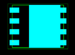
Do you agree that the recommended footprint on page 4 of the SBRT25U80SLP diode datasheet is incorrect?
The long sides of the SBRT25U80 diode have metal protrusions sticking out of them, which emenate from the large main pad of the SBRT25U80 diode.
However, the recommended footprint does not offer a metal pad for these bits of protrusion. Worse still, if one were to use the recommended footprint shown, then there would be solder resist under those “lateral protrusions”. This solder resist would partially melt during surface mount flow soldering, and would “stick” to the lateral protrusions, and thus prevent the component from “settling” onto its pads….thus meaning improper soldering.
Do you agree, the shown recommended footprint needs to be extended to take into account the lateral protrusions to the main pad of the SBRT25U80SLP diode?
Datasheet : SBRT25U80SLP diode
**broken link removed**


