Continue to Site

Welcome to EDAboard.com

Welcome to our site! EDAboard.com is an international Electronics Discussion Forum focused on EDA software, circuits, schematics, books, theory, papers, asic, pld, 8051, DSP, Network, RF, Analog Design, PCB, Service Manuals... and a whole lot more! To participate you need to register. Registration is free. Click here to register now.

Sensitivity lists syntax in VHDL and Verilog

Status
Not open for further replies.

dstr

Newbie level 2
Newbie level 2
Joined
Aug 12, 2014
Messages
2
Helped
0
Reputation
0
Reaction score
0
Trophy points
1
Activity points
21
Hi all,


Let's suppose that I want to implement a AND gate with registered output.

Googling for examples I found this:


Verilog:

Code:
always @(posedge clk or posedge reset)
begin
    if (reset)
        output <= 1'b0;
    else
        output <= a & b;
end

In VHDL I would write like that:

Code:
process (clk, reset)
begin
    if (reset = '1') then
        output <= '0';
    elsif rising_edge(clk) then
        output <= a AND b;
    end if;
end;

My first question is:
In VHDL I must explicitly test both 'reset' and 'clk'.
In Verilog testing 'reset' is enough! Why?


My second question is:

In Verilog I can't mix in the same sensitivity list, both level-sensitivity and edge-sensitivity signals.

Giving that constraint, how can I implement in Verilog, the equivalent of the VHDL code below:

Code:
process (a, b, c)
begin
    if rising_edge(a) then
        output <= b AND c;
    end if;
end;


Thank you

Danis
 
Last edited:

My first question is:
In VHDL I must explicitly test both 'reset' and 'clk'.
In Verilog testing 'reset' is enough! Why?

In Verilog there is no need to explicitly test at clocking edge,in above code else statement is executed in synchronous to clocking edge(posedge of clock).suppose if you have more number of edge sensitivity list like in the fallowing code
Code:
always @(posedge clk or posedge reset or posedge enable)
begin
    if (reset)
        output <= 1'b0;
    else if (enable)
        output <= 1'b1;
	else
		output <=a & b;
end
First it will look for posedge of reset if it is false,then it will look for posedge of enable if it is also false then
last else statement is executed in synchronous to clock edge only.

I think the "posedge enable" should be removed from the sensitivity list.
One "glitch" with Verilog is that "posedge reset" in the sensitivity list will not make it edge sensitive. When synthesized, it will be a level sensitive (asynchronous) reset. If you want a synchronous reset, remove "posedge reset" from the sensitivity list (keeping only the "posedge clk").
 
I think this discussion throws up some of the subtle differences between verilog and vhdl.

VHDL's sensitivity list is just a list of signals where the 'event attribute is monitored. When ANY 'event occurs, the process is re-evaluated, and you have to test to see what 'event actually occured if you care about more than one signal.

Your final example is not valid, as the output will only ever change at the rising edge of a, so b and c are not needed in the sensitivity list.

In verilog, the @ is simply a timing control statement. you can put it in most places:

Code:
intial
begin
  reset = repeat(5) @(negedge clock) 1;
  reset = @(negedge clk) 0;
end
 

In Verilog there is no need to explicitly test at clocking edge,in above code else statement is executed in synchronous to clocking edge(posedge of clock).suppose if you have more number of edge sensitivity list like in the fallowing code
Code:
always @(posedge clk or posedge reset or posedge enable)
begin
    if (reset)
        output <= 1'b0;
    else if (enable)
        output <= 1'b1;
	else
		output <=a & b;
end
First it will look for posedge of reset if it is false,then it will look for posedge of enable if it is also false then
last else statement is executed in synchronous to clock edge only.
Besides what std_match mentions about the level sensitivity of the reset signal there are other problems with this example.
output is a keyword and can not be used as a signal name.
the addition of posedge enable while syntactically correct doesn't represent any kind of actual hardware and is therefore not synthesizable.

Take for instance this code, which shows how the Verilog sensitivity list behaves

Code Verilog - [expand]
1
2
3
4
5
6
7
8
9
10
11
12
13
14
15
16
17
18
19
20
21
22
23
24
25
26
27
28
29
30
31
32
33
34
35
36
37
38
39
40
41
42
43
44
45
46
47
48
49
50
51
52
53
54
55
module test2 ();
 
reg [1:0] out;
reg a;
reg b;
reg clk;
 
initial begin
  clk = 1;
  forever clk = #500 ~clk;
end
 
initial begin
  a = 0;
  b = 0;
  #100;
  a = 0;
  b = 1;
  #100;
  a = 1;
  b = 1;
  #100;
  a = 1;
  b = 0;
  #100;
  a = 0;
  b = 0;
  #100;
  a = 1;
  b = 0;
  #100;
  a = 1;
  b = 1;
  #100;
  a = 0;
  b = 1;
  #100;
  a = 0;
  b = 0;
end
 
always @ (posedge clk or a or b) begin
  if (!a && !b) begin
    out <= 0;
  end else if (!a && b) begin
    out <= 1;
  end else if (a && !b) begin
    out <= 2;
  end else begin
    out <= 3;
  end
  $display ("%t - ab = %b", $time, out);
end
 
endmodule


The output will look like this:
Code:
                   0 - ab = xx
                 100 - ab = 00
                 200 - ab = 01
                 300 - ab = 11
                 400 - ab = 10
                 500 - ab = 00
                 600 - ab = 10
                 700 - ab = 11
                 800 - ab = 01
                1000 - ab = 00
                2000 - ab = 00
                3000 - ab = 00
As you can see not using posedge (or negedge) still results in the always block block being scheduled for changes in a and b. Note: the clock rising edges occur at 1000, 2000, and 3000.

There is nothing in the Verilog language that prevents you from using the following for a active high asynchronous reset.

Code Verilog - [expand]
1
2
3
always @ (posedge clk or reset)
  if (reset)  out <= 0;
  else        out <= in;


The problem here is the falling edge of reset will also trigger the always block which will then asynchronously assign out with the current in value. Adding the posedge in front of the reset prevents this from occurring as the only time the always block is triggered on the asynchronous reset is when it enters reset (the leading rising edge) after that the reset is treated as a level signal (which is the case for all signals in a clocked, @(posedge clk), always block).

I hope this helps clarify the behavior of edge vs level sensitivity.

Regards
 
The verilog construct has been misinterpreted, I think. Replacing the reserved keyword output by a legal name, you get a synthesizable text book example of a synchronous register with asynchronous clear and preset. In case of doubt, review IEEE Std 1364.1.

Code Verilog - [expand]
1
2
3
4
5
6
7
8
9
always @(posedge clk or posedge reset or posedge enable)
begin
    if (reset)
        out <= 1'b0;
    else if (enable)
        out <= 1'b1;
    else
        out <=a & b;
end


It can't be implemented in a single logic element by some recent FPGA families, but is synthesizable anyway.
 
FvM you're are right, thanks for pointing out my mistake.

Functionally the enable signal isn't an enable, which I didn't notice as I never looked at the out <= 1'b1 assignment, and am not used to seeing code with both async set/reset.

Also I never code stuff like this as both Altera and Xilinx have obsoleted all their devices that directly support both an asynchronous set and reset that can be used simultaneously (like Xilinx's old 3000 series devices).
 

Also I never code stuff like this as both Altera and Xilinx have obsoleted all their devices that directly support both an asynchronous set and reset that can be used simultaneously (like Xilinx's old 3000 series devices).
Yes, you better avoid it with recent FPGAs. Asynchronous set/reset or asynchronous preload will be emulated by an unpleasant construct with latches and XORs around the register.
 

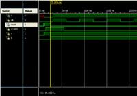
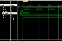
With above discussion i came to know that asynchronous control signals reset ,enable are all level sensitive unlike edge sensitive ,even though we specify them as edge sensitive in sensitivity list .But still they are not level sensitive as far as simulations are concerned.In simulations they look for edge only.Below program is a simple asynchronous reset,preset (enable ) type register.I dont know whether this type of register is used generally or not,i tested for two cases i assigned two control signals reset ,enable asynchronously .The code works like a priority logic ,i attached test bench and simulation results.In first case at 25ns i am realising reset to low but not enable signal but according to std_match suggestion the output signal c must be assigned to 1 (because enable is high )but still it is in reset state only.In second case i am setting enable high as soon as reset becomes low then in that case it is giving output as 1'b1 (that means for a positive edge change).
Code:
module simple_and(
    input clk,
    input reset,
    input enable,
    input a,
    input b,
    output reg c
    );
	
	always @ (posedge clk,posedge reset,posedge enable)
		if (reset)
			c<=1'b0;
		else if (enable)
			c<=1'b1;
		else
			c<= a & b;


endmodule
Code:
module tb_sim_and;

	// Inputs
	reg clk;
	reg reset;
	reg enable;
	reg a;
	reg b;

	// Outputs
	wire c;

	// Instantiate the Unit Under Test (UUT)
	simple_and uut (
		.clk(clk), 
		.reset(reset), 
		.enable(enable), 
		.a(a), 
		.b(b), 
		.c(c)
	);

	initial begin
		// Initialize Inputs
		clk = 0;
		reset = 0;
		enable = 0;
		a = 0;
		b = 0;
		#10;
		reset= 1'b1;
		enable =1'b0;
		a<=1'b1;
		b<=1'b0;
		#4;
		reset= 1'b1;
		enable =1'b1;
		a<=1'b1;
		b<=1'b0;
		#4;
		reset= 1'b1;
		enable =1'b1; //for case 2 enable= 1'b0;then it becomes 0 to 1 transition when reset becomes low
		a<=1'b1;
		b<=1'b0;
		#7;
		reset= 1'b0;
		enable =1'b1;
		a<=1'b1;
		b<=1'b1;
		#30;
		reset= 1'b0;
		enable =1'b0;
		a<=1'b1;
		b<=1'b1;

	end
	
	always #30 clk = ~ clk;
      
endmodule

 
  • Like
Reactions: FvM

    FvM

    Points: 2
    Helpful Answer Positive Rating
With above discussion i came to know that asynchronous control signals reset ,enable are all level sensitive unlike edge sensitive ,even though we specify them as edge sensitive in sensitivity list .But still they are not level sensitive as far as simulations are concerned.In simulations they look for edge only.
Did you read my post #5? If you don't add the posedge for reset then enable (poor choice of name it is a set or preset) statement will be taken when the falling edge of reset occurs. Why don't you try running my testcase and look at the outputs and when they occur.

Below program is a simple asynchronous reset,preset (enable ) type register.I dont know whether this type of register is used generally or not,i tested for two cases i assigned two control signals reset ,enable asynchronously.
Did you read our comments in #6, #7, and #8 about using registers with both asynchronous reset/preset? If you are developing for an ASIC that has async reset/preset registers in the library then fine go ahead and use them (though I don't see the necessity of using such a logic element, unless you like trying to develop constraints for asynchronous designs and getting them to meet timing). As your original post is in the programmable logic area and current generation FPGAs don't have both async reset/preset (simultaneous), we recommend you avoid using such constructs as they produce some ugly external logic around the register to create the appearance of having both async inputs.

Regards
 

Interesting observation. Using edge-sensitive events for level-sensitive functions always seemed counter-intuitive to me. But it's required by IEEE Std 1364.1 and has been adopted by Verilog synthesis tools before the Verilog RTL synthesis standard was released.

If I understand right, there's essentially one simulation to synthesis mismatch in your first testbench. The preset ("enable") input should immediately become effective when reset is deasserted. In other words, reset must be sensitive for both edges. I see no mismatch for the second testbench.
 

Using edge-sensitive events for level-sensitive functions always seemed counter-intuitive to me.
Well VHDL suffers from the same issue, they just hid it by forcing one to include extra statements in the process body that says the signal in the sensitivity list is edge or level. The signals in the sensitivity list still trigger the process on their transitions (i.e. edges).

Verilog allows you to combine the edge sensitivity in the sensitivity list by adding posedge, so it doesn't have to appear in the body of the always block. Level signals on the other hand always appear in the always block and only require edge sensitivity when they are treated as asynchronous inputs.
 

Well VHDL suffers from the same issue, they just hid it by forcing one to include extra statements in the process body that says the signal in the sensitivity list is edge or level. The signals in the sensitivity list still trigger the process on their transitions (i.e. edges).
The sensitivity list in VHDL has no effect for synthesis. The synthesized function is fully specified by the body. The sensitivity list is only a help to reduce the simulation time. For synthesizeable code an output can not change without an input change, so it is logical that the simulator only executes a process when there is an input edge.

How can you in Verilog describe a clocked register with both asyncronous set and reset? You need "posedge reset" in the sensitivity list to avoid setting the output at the negative edge, but if "set" is active the simulator must execute the process at the negative edge of reset (if reset has higher priority than set).
 

How can you in Verilog describe a clocked register with both asyncronous set and reset? You need "posedge reset" in the sensitivity list to avoid setting the output at the negative edge, but if "set" is active the simulator must execute the process at the negative edge of reset (if reset has higher priority than set).
I don't exactly understand what this comment means related to the problem presented in post #9.

The code is correct according to the Verilog template for synchronous registers with multiple asynchronous inputs.

Code Verilog - [expand]
1
2
3
4
5
6
7
8
9
always @(posedge clk or posedge reset or posedge enable)
begin
    if (reset)
        out <= 1'b0;
    else if (enable)
        out <= 1'b1;
    else
        out <=a & b;
end


But as kommu4946 revealed, it involves a simulation mismatch issue. You would need something like an additional negedge event for the higher priorized asynchronous input to achieve compliant simulation.

The equivalent VHDL register construct doesn't involve a similar issue.
 

Status
Not open for further replies.

Similar threads

Part and Inventory Search

Welcome to EDABoard.com

Sponsor

Back
Top