Continue to Site

Welcome to EDAboard.com

Welcome to our site! EDAboard.com is an international Electronics Discussion Forum focused on EDA software, circuits, schematics, books, theory, papers, asic, pld, 8051, DSP, Network, RF, Analog Design, PCB, Service Manuals... and a whole lot more! To participate you need to register. Registration is free. Click here to register now.

Using some capacitors before a transistor to bias it for RF power amplifiers

Status
Not open for further replies.

f_t

Member level 4
Member level 4
Joined
Jun 30, 2014
Messages
75
Helped
1
Reputation
2
Reaction score
1
Trophy points
8
Visit site
Activity points
633
Hello,

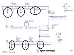
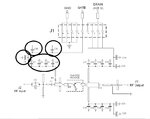
I am designing a Class-E power amplifier. As I looking at these circuits there are some capacitors on the root of biasing transistors. Could you please say why these capacitors have been used and how we should calculate their value to use them in our circuits?
I have attached two circuits. The first one is from Agilent and the other one 111.jpg1111.jpgis from Cree.
Thanks a lot
 

The capacitors with inductors form low-pass filters, to prevent RF and AC signals coupling back to DC power supplies.
Using several capacitor values in parallel is recommended for blocking a wide frequency spectrum. High-capacitance capacitors (like 1...100 uF) have certain inductance, so using ceramic capacitors in parallel improves filtering for a wide frequency band.
Good blocking is needed due to low-impedance amplifier structure.
 
  • Like
Reactions: f_t

    f_t

    Points: 2
    Helpful Answer Positive Rating
I think it is helpful to clean the DC input by filtering with it.
 

The capacitors with inductors form low-pass filters, to prevent RF and AC signals coupling back to DC power supplies.
Using several capacitor values in parallel is recommended for blocking a wide frequency spectrum. High-capacitance capacitors (like 1...100 uF) have certain inductance, so using ceramic capacitors in parallel improves filtering for a wide frequency band.
Good blocking is needed due to low-impedance amplifier structure.

You are right my friend, but, how exactly we should calculate their amounts? For example, consider we have 28 volt supply voltage for drain and -2.5 volt for gate and we are working at 2.3 to 2.3 GHz frequency band (Second Photo).
 

You are right my friend, but, how exactly we should calculate their amounts? For example, consider we have 28 volt supply voltage for drain and -2.5 volt for gate and we are working at 2.3 to 2.3 GHz frequency band (Second Photo).

As E-class amplifiers also use PWM to operate, it is a good idea to design a low-pass filter that rejects all unwanted spectrum components (first diagram) The second diagram only utilizes several capacitors in parallel to filter the RF spectrum.

Where inductors are used, they form poles in filter response as needed. You will have to study filter design to understand all details.
 
  • Like
Reactions: f_t

    f_t

    Points: 2
    Helpful Answer Positive Rating
Status
Not open for further replies.

Part and Inventory Search

Welcome to EDABoard.com

Sponsor

Back
Top