Continue to Site

Welcome to EDAboard.com

Welcome to our site! EDAboard.com is an international Electronics Discussion Forum focused on EDA software, circuits, schematics, books, theory, papers, asic, pld, 8051, DSP, Network, RF, Analog Design, PCB, Service Manuals... and a whole lot more! To participate you need to register. Registration is free. Click here to register now.

designing high voltage smps with llc

Status
Not open for further replies.

tictac

Full Member level 5
Full Member level 5
Joined
Oct 22, 2006
Messages
297
Helped
3
Reputation
6
Reaction score
3
Trophy points
1,298
Location
Polland
Visit site
Activity points
3,572
hi
I want to design the smps with below specifications:

Vin=220 Vac
Vout=1KV to 30KV , Iout-max= 20mA

I want to use LLC for it. Is it possible to use LLC for this converter? I want to calculate resonance elements and transformer turn ratio and primary and secondary turns and inductances. The maximum voltage and current that drop on resonance elements at the primary side. Is there anybody to help me for calculating its parameters?

Regards.
 

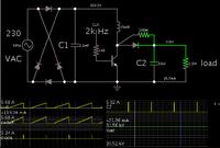
As a starting point, here is a (theoretical) simulation of a boost converter which steps up rectified house current to 30 kV.

At 20mA, the load calculates to be 1.5 M ohms.
Power is 600 W.

The plan is feasible only if you can produce a coil (or transformer) which is able to endure this great a voltage, without arcing between the windings.

You can use a higher frequency than 2kHz, and a smaller inductor than 20mH.


I'm not familiar with resonant LLC topology. I see this article speaks of many advantages.

https://www.fairchildsemi.com/an/AN/AN-4151.pdf
 
Hello there, how about a resonant flyback with 6 transformers each providing 5kV, in series, to get your 30kV, 100W per transformer, 15kHz so you can hear it going (safety) primaries in parallel, sec's in series...
Regards, Orson.
 
hi
I want to design the smps with below specifications:

Vin=220 Vac
Vout=1KV to 30KV , Iout-max= 20mA

I want to use LLC for it. Is it possible to use LLC for this converter? I want to calculate resonance elements and transformer turn ratio and primary and secondary turns and inductances. The maximum voltage and current that drop on resonance elements at the primary side. Is there anybody to help me for calculating its parameters?

Regards.
Hi Tictac
one of the most usual ways to yield variable high voltage PSU , is using a push pull converter to make 5 KV and then using an RCD voltage multiplier . and take the feedback from the main out put . change the feedback ration you'll get variable HV . but be careful this procedure is absolutely dangerous and you'll deal with a lot of hazard .
Best Wishes
Goldsmith

- - - Updated - - -

As a starting point, here is a (theoretical) simulation of a boost converter which steps up rectified house current to 30 kV.

At 20mA, the load calculates to be 1.5 M ohms.
Power is 600 W.

The plan is feasible only if you can produce a coil (or transformer) which is able to endure this great a voltage, without arcing between the windings.

You can use a higher frequency than 2kHz, and a smaller inductor than 20mH.


I'm not familiar with resonant LLC topology. I see this article speaks of many advantages.

http://www.fairchildsemi.com/an/AN/AN-4151.pdf

Hi Bradtherad
To be honest i've never saw such a simple circuit that can do such an amazing thing ! again i'm learning new things from you . i tested the circuit that you have mentioned in your post it works fine . thank you very much for that .
Sincerely
Goldsmith
 

Hi BradtheRad
Thanks you for a good circuit. can you give the part number for transistor ? I think high voltage can drop on the collector of the transistor, isnt it?
I want to build my circuit with LLC. I want to know about the possibility of making such a high voltage smps with variable output by using LLC. I want to use one transformer with multiple secondary windings (4 x8kv) and one primary windings.
Is there any body for helping me to build it with LLC,please?

and thanks you Mr goldsmith.
 

Hello tictac, I don't want to hijack your Post.

I'm facing a very similar problem like you.
I'm a student and trying to designing a High Voltage Power-Supply to use for paper filter perforation with electric arcs.
My Output requirement is about 10kVpp (AC) and should have current regulation from 0 to 20mA peak.

I'm using for my input a stable 24V.

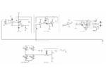
In the attachment I send the actual stage of my design.
E_schema.png

I'm using a BUCK Converter attached to an 12kHz oscillating H-Bridge.
I have no experience in feedback designs and kind like to ask for help of finding the right values.

Kind regards
 

Why would you want to use LLC for such a purpose? I doubt you'll get good efficiency operating at such a high voltage and low current, due to magnetizing losses in the transformer.
 

Hi BradtheRad
Thanks you for a good circuit. can you give the part number for transistor ? I think high voltage can drop on the collector of the transistor, isnt it?

I am not certain my (theoretical) simulation will work with real components, at such high voltages. It is helpful for getting an idea of the voltage and current levels involved.

As you state, the transistor collector will be exposed to 30 kV. I'm not familiar with components that handle this. I picture sparks occurring across the legs of the transistor.

It is preferable to avoid making single components do this job. Better to string components in series, each contributing a lesser voltage.

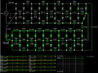
Example, the Cockcroft-Walton voltage multiplier is a popular method.

This simulation has ten stages, powered by house current.


The screenshot was snapped just as current is being drawn from the AC supply.

Several hundred mA are needed per cycle, to maintain a few mA across the 1M ohm load.

The 100 uF capacitors can be electrolytics, rated for 400VDC.

(Experimenters often use smaller values because the high voltages are often at tiny ampere levels. As for me I would be afraid to get too close to 30kV at 20mA. A mere 1 mA through our body can be fatal.)

It would work well if you were to use a transformer (or autoformer) to step up house current 2 or 3 times, then apply it to a C-W topology.
 
Why would you want to use LLC for such a purpose? I doubt you'll get good efficiency operating at such a high voltage and low current, due to magnetizing losses in the transformer.
One of important reasons for using LLC is to omit secondary inductor filter because of existence of high voltage at the secondary side .
Another reason is zvs and soft switching at the primary side.
 

Hello there, presumably you need an isolating topology to get isolation from the 220Vac mains input, if you do this you may as well use the topology to control the o/p as well, up to 30kV, 20mA, I am assuming you want the o/p volts constant with varying load (up to 20mA), unfortunately the voltage multiplier will not do this (it will sag with load for a constant input). Also a little known property of LLC is that you will have to go extremely high in freq (as mentioned above) to drop the o/p volts below half of max. Also there is a limit to the amount of current limiting you can get with LLC.
We have built 10kV units using a single flyback transformer and 5 o/p's of 2kV each, connected in series, extremely simple and reliable, and immune to o/p short. Easy enough to extend this to 2 x 15kV units at 300W each (giving 30kV in series op) , because of the speed of the o/p rectifying diodes (i.e. slow) the freq for hard switching would need to be below 100kHz, unless you use a resonant flyback, which might allow 50-75kHz without too much trouble... (i.e. heat in the o/p diodes) p.s. if you are series-ing o/p diodes to get higher piv (e.g. BYV26E 1kV) don't forget that a small snubber across each (with suitably rated R's & C's) will help keep the piv balanced at diode turn off
Regards,
Orson.
 
I am not certain my (theoretical) simulation will work with real components, at such high voltages. It is helpful for getting an idea of the voltage and current levels involved.

As you state, the transistor collector will be exposed to 30 kV. I'm not familiar with components that handle this. I picture sparks occurring across the legs of the transistor.
Hi Bradtherad
One of the methods for achieving a high voltage transistor is using them in series together it can allow us to increase the VCE as well .
Anyway , the idea which you've presented is based on a boost converter but i didn't even think that it can be obtained by that pretty simple circuit . by the way , for the voltages up to 10 kv that circuit seems so reasonable .

As for RCD multipliers , i've did a funny thing some years ago . i've used a color TV , HV transformer and then a multistage RCD multiplier and the out put voltage became 55 kv it was amazing !

The 100 uF capacitors can be electrolytics, rated for 400VDC.
I usually use Y2X2 capacitors for these purposes they can easily handle this with lower capacity .

It always amazes me that many of the times you're doing everything as simple as possible and i take many ideas from your designs and learning from you always .


Hi
Is there any body to help me for completing of this smps?
Regards
Hi
As you see we are all here , tell me what is your deduction by our explanations and why you're ganging ? then we can give you more help .

Best Wishes to all
Goldsmith
 

Status
Not open for further replies.

Similar threads

Part and Inventory Search

Welcome to EDABoard.com

Sponsor

Back
Top