Continue to Site

Welcome to EDAboard.com

Welcome to our site! EDAboard.com is an international Electronics Discussion Forum focused on EDA software, circuits, schematics, books, theory, papers, asic, pld, 8051, DSP, Network, RF, Analog Design, PCB, Service Manuals... and a whole lot more! To participate you need to register. Registration is free. Click here to register now.

[SOLVED] LCD display show garbage

Status
Not open for further replies.

Golden Electronics

Full Member level 5
Full Member level 5
Joined
May 31, 2013
Messages
308
Helped
50
Reputation
100
Reaction score
47
Trophy points
1,318
Location
India
Visit site
Activity points
2,730
Recently I develop one project in which total 6 AC motor & one 2KW Heater. The project contain 16x2 LCD display with PIC16F886. When use press key then 2 motor on at a time. Also Heater cont on-off to maintain temperature. During trial I observe that after some key operation LCD show garbage & it remain few minute & back to normal display. During key operation LCD message change. I also isolate all AC part from controller with isolation. Motor drive using Relay & heater drive using triac. LCD in 4 bit mode.

Can any one face such problem then inform any idea...
 

I use regulated power supply with sufficient filter cap & it not shown here. I shown single relay circuitry but same use for other also
 

Attachments

  • PAGE.pdf
    19.9 KB · Views: 333
Is the regulated 5V supply derived from the 12V line?

Can you elaborate on the power supply specifics, relationship of 5V and 12V supplies and the relay specifications?

Post a schematic of that part of the design if available.

Are the LM324s operating in single supply 5V?


BigDog
 

Is the regulated 5V supply derived from the 12V line?

Can you elaborate on the power supply specifics, relationship of 5V and 12V supplies and the relay specifications?

Post a schematic of that part of the design if available.

Are the LM324s operating in single supply 5V?


BigDog

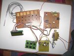
For LM324 i use 5 V. I attach power supply circuit with photo
 

Attachments

  • page2.pdf
    7.2 KB · Views: 198
  • one.JPG
    one.JPG
    443 KB · Views: 204

After examining your schematics and the photo, I'm leaning towards relay EMI interfering with the microcontroller or LCD.


Is the bypass/decoupling capacitor across the VDD and VSS of the microcontroller shown on the schematic a 100nF?

Is there bypass/decoupling capacitor across the VDD and VSS of the LCD?

If not you might try utilizing a bypass/decoupling capacitor(s) for the LCD.

You might try three caps in parallel something like, 1nF, 100nF and 4.7uF. The single 100nF bypass/decoupling cap is not as effective in filtering out the low frequency interference possible from a relay.


You may also need to deploy EMI suppression/RC Snubber networks across the contact terminals of the relays particularly if there are currently no snubber networks across the motor terminals.

The application of relay coil suppression with DC relays

R-C Snubber Noise and Arc Suppressor

What are the specs of the motors controlled by the relays? Are there snubber networks across the motor terminals?


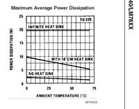
Also I would recommend deploying heatsinks on the LM7805/LM7812 T-220s, without heatsinks the regulators' max power dissipation and the associated max current output will be drastically limited, depending on the ambient temperature possibly less than 2W.


After all, the 12V supply is driving up to six relays and their driver circuits, the current requirements add up quickly.


Future reference, a possible better design would have been to locate the relays, their driver circuits, BT136, MOC3021 and snubber circuit on one PCB and the microcontroller along with signal conditioning opamp circuits on another.


BigDog
 
  • Like
Reactions: mkbutan

    mkbutan

    Points: 2
    Helpful Answer Positive Rating
    V

    Points: 2
    Helpful Answer Positive Rating
Thanks for reply BigDog...


Yesterday I make many trial & display not show any garbage... I make many changes before trial (SW & HW)........ I again check each point again & inform which solution applicable to such issue..........
 

After examining your schematics and the photo, I'm leaning towards relay EMI interfering with the microcontroller or LCD.


#01 You might try three caps in parallel something like, 1nF, 100nF and 4.7uF. The single 100nF bypass/decoupling cap is not as effective in filtering out the low frequency interference possible from a relay.


#02 After all, the 12V supply is driving up to six relays and their driver circuits, the current requirements add up quickly.


#03 Future reference, a possible better design would have been to locate the relays, their driver circuits, BT136, MOC3021 and snubber circuit on one PCB and the microcontroller along with signal conditioning opamp circuits on another.


BigDog


Hi,
sir, I am new to Microcontrolers and its Programming..
there is no doubt you have given the best ans.
but sir, I would like to ask you few Questions

#01 I'm leaning towards relay EMI interfering with the microcontroller or LCD.

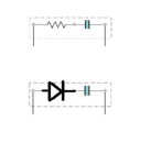
I dont know much but ,,, if we replace the Resistance with the Diode is it not sufficient (say IN4007 and 1nf) will it not suppress the EMI of the Relays'

RC vs DC.png

#02 You might try three caps in parallel something like, 1nF, 100nF and 4.7uF.
Please Explain the Theory and Practical use of it

#03 the 12V supply is driving up to six relays and their driver circuits

LM7805/6/8/9/10/12/15/18/24
3-Terminal 1A Positive Voltage Regulator

The LM78XX series of three terminal positive regulators are
available in the TO-220 package and with several fixed output
voltages, making them useful in a wide range of applications.
Each type employs internal current limiting, thermal shut down
and safe operating area protection, making it essentially indestructible.
If adequate heat sinking is provided, they can deliver
over 1A output current. Although designed primarily as fixed
voltage regulators, these devices can be used with external
components to obtain adjustable voltages and currents.

now do we need more then 1A of current to drive the 6 Relays??

Please explain

#04 Future reference, a possible better design would have been to locate the relays, their driver circuits, BT136, MOC3021 and snubber circuit on one PCB and the microcontroller along with signal conditioning opamp circuits on another.

sir what if want to have all the Sections on in one PCB and why do we need to separate them??

thanks in advance
 

Attachments

  • RC vs DC.png
    RC vs DC.png
    13.3 KB · Views: 166

#01 I'm leaning towards relay EMI interfering with the microcontroller or LCD.

I dont know much but ,,, if we replace the Resistance with the Diode is it not sufficient (say IN4007 and 1nf) will it not suppress the EMI of the Relays'

Electromagnetic Interference (EMI) is not reliant on wires or copper traces to propagate, it is the typically unintentional generation of electromagnetic waves/energy which can propagate the air like Radio Frequency (RF) or Electromagnetic Pulse (EMP).

In the case of the above design probable sources of EMI are the relay contacts and the motors being controlled.

The RC network across the output of the TRIAC is essentially a snubber network designed to counter EMI produced by the TRIAC switching On/Off, as well as the load, the motor being controlled.

While the diode across the relay coil, is intend to safely channel Back EMF or Fly Back Voltage as it is commonly referred. Such Back EMF occurs when the magnetic field of a inductor, like the relay coil, suddenly collapses generating a large voltage transient.

The issues are two different and distinct problems with which must be dealt accordingly.

EMI can be received by wires, copper traces and components of the design and in turn can produce transients and noise on various signal paths with adverse effects.

Common Electromagnetic Compatibility (EMC) are bypass/decoupling capacitors, snubber circuits, shielding, proximity, solid state relays, multiple proper ground planes, ferrite beads, etc.

#02 You might try three caps in parallel something like, 1nF, 100nF and 4.7uF.
Please Explain the Theory and Practical use of it

Capacitors of differing composition and values react differently to various frequencies and characteristics of various EMI sources.

By ganging several different capacitors in parallel of different values and composition, the group can bypass/decouple a wider range of EMI.

#03 the 12V supply is driving up to six relays and their driver circuits

now do we need more then 1A of current to drive the 6 Relays??

Perhaps, it largely depends on the specifications of the relays being utilized in the design.

The important point I was attempting to convey is that without proper heatsinks linear regulators, like LM7805 and LM7812, the maximum heat dissipation drops sharply and so too does the available current.

#04 Future reference, a possible better design would have been to locate the relays, their driver circuits, BT136, MOC3021 and snubber circuit on one PCB and the microcontroller along with signal conditioning opamp circuits on another.

sir what if want to have all the Sections on in one PCB and why do we need to separate them??

As explain in response to your first question, sources of EMI, in this case the relay contacts, can be somewhat countered increasing proximity/distance from the EMI sources.

The design could be placed on a single PCB, however more thorough EMC measures maybe required, like shielding, grounded Cans over the sensitive components, etc which you can often observe in various RF and test equipment.

Another option is to utilize solid state relays in place of the mechanical relays which will alleviate much of the EMI from the relay contacts.

You can Google most of the topics for a more in depth discussion and there are numerous publications available which deal with each topic exclusively.

BigDog
 
  • Like
Reactions: mkbutan

    mkbutan

    Points: 2
    Helpful Answer Positive Rating
As per result it is due to wire length. I use flat ribbon cable which is around 8-10 cm away from LCD. I just remove this cable with new FRC cable having length 2-3 cm. Now it work ok for more than 5000 cycle.
 

Hi,

Don't let your bench testing fool you.

In addition to the all very detailed points BigdogGuru has given, you really need to eliminate as many areas as possible.

A well designed pcb is probably the biggest improvement to having all those loose wires.

The most obvious source is the long leads on the keypad which from practical experience are more likely to be causing a problem.

Connections like those should be made with shielded cable, with the shield connected at one end to Earth.

As BDG metioned you can use a variety of components to act as input filters to these lines as well.
 
  • Like
Reactions: bigdogguru

    bigdogguru

    Points: 2
    Helpful Answer Positive Rating
    V

    Points: 2
    Helpful Answer Positive Rating
I make some hardware & software changes such as
1. Remove LCD Clear display function
2. Also increase delay between LCD display routine
3. LCD Read pin control via software instead of making hard ground
 
Last edited:

Status
Not open for further replies.

Similar threads

Part and Inventory Search

Welcome to EDABoard.com

Sponsor

Back
Top