dhruv_electro
Advanced Member level 4

Hi,
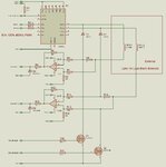
Our basic need is to open solenoid(s) 0 to 100% using MCU. Functional description of hardware is listed below.
1. Total no of solenoid to operate is 12.
2. Current source can very from 0-500mA (please see attchment).

3. Current sensing is needed only for Over and Under current protection and error generation.
4. Available supply rails are 24VDC, 12VDC and 5VDC.
5. Any time One or Two Solenoid is functioning, rest will be in OFF (complete closed) mode.
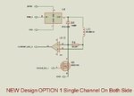
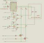
The attachment contains two PWM, 1 for Coarse tuning and 1 for Fine Tuning. This is done because there are two type of solenoid, when we tested using controlled current source, 24VDC first one starts opening at 350mA and at 450mA it is fully opened. Other one starts at 200mA and Fully Opened at 350mA. We wanted to have control of 0-100% operation. So we decided to have a coarse tuning and a fine tuning PWM, fine tuning will take care for full 0-100% range, and coarse PWM provide basic current, Later we will use AND gate network to enable multiple solenoid. I think this method is Current Controlled. Basic query is for how solenoid should be driven for 0 to 100% operation, are we on right track? Or we are doing complex solution when there may be other options available?? like many top level members suggested in this post:
https://www.edaboard.com/threads/130480/
We don't know what to call but these may be voltage controlled options, Is it suit us? Here we needed to provide current feedback for Over and Under current errors.
We have done some digging if any other options available, so we have this special ICs from TI:
1. **broken link removed** (with Over current Under current and Thermal Protection / fault indication)
2. DRV103 (with Over current and Thermal Protection / fault indication)
Both are using a PWM Duty cycle control Input which can take Analog Voltage (DRV101 : 0.75-3.7V for 90%-10% and DRV103 :1.3V-3.9 10% to 90%) with that we can control Solenoid and pain will be lesser, But both are quite costlier, and DRV103 is not providing under current indication. Is it ok if we go for this kind of options? (Price of hardware is over budget if we are using it for 12 channels.) Or would you suggest other solutions for our need?
Thanks in advance.
- - - Updated - - -
Meanwhile we got the all different solenoids and measured the coil resistance:
1. 42 Ohms
2. 53 Ohms
3. 68 Ohms
Our basic need is to open solenoid(s) 0 to 100% using MCU. Functional description of hardware is listed below.
1. Total no of solenoid to operate is 12.
2. Current source can very from 0-500mA (please see attchment).

3. Current sensing is needed only for Over and Under current protection and error generation.
4. Available supply rails are 24VDC, 12VDC and 5VDC.
5. Any time One or Two Solenoid is functioning, rest will be in OFF (complete closed) mode.
The attachment contains two PWM, 1 for Coarse tuning and 1 for Fine Tuning. This is done because there are two type of solenoid, when we tested using controlled current source, 24VDC first one starts opening at 350mA and at 450mA it is fully opened. Other one starts at 200mA and Fully Opened at 350mA. We wanted to have control of 0-100% operation. So we decided to have a coarse tuning and a fine tuning PWM, fine tuning will take care for full 0-100% range, and coarse PWM provide basic current, Later we will use AND gate network to enable multiple solenoid. I think this method is Current Controlled. Basic query is for how solenoid should be driven for 0 to 100% operation, are we on right track? Or we are doing complex solution when there may be other options available?? like many top level members suggested in this post:
https://www.edaboard.com/threads/130480/
We don't know what to call but these may be voltage controlled options, Is it suit us? Here we needed to provide current feedback for Over and Under current errors.
We have done some digging if any other options available, so we have this special ICs from TI:
1. **broken link removed** (with Over current Under current and Thermal Protection / fault indication)
2. DRV103 (with Over current and Thermal Protection / fault indication)
Both are using a PWM Duty cycle control Input which can take Analog Voltage (DRV101 : 0.75-3.7V for 90%-10% and DRV103 :1.3V-3.9 10% to 90%) with that we can control Solenoid and pain will be lesser, But both are quite costlier, and DRV103 is not providing under current indication. Is it ok if we go for this kind of options? (Price of hardware is over budget if we are using it for 12 channels.) Or would you suggest other solutions for our need?
Thanks in advance.
- - - Updated - - -
Meanwhile we got the all different solenoids and measured the coil resistance:
1. 42 Ohms
2. 53 Ohms
3. 68 Ohms


