Continue to Site

Welcome to EDAboard.com

Welcome to our site! EDAboard.com is an international Electronics Discussion Forum focused on EDA software, circuits, schematics, books, theory, papers, asic, pld, 8051, DSP, Network, RF, Analog Design, PCB, Service Manuals... and a whole lot more! To participate you need to register. Registration is free. Click here to register now.

[MOVED] circuit related questions

Status
Not open for further replies.

khangzing

Full Member level 2
Full Member level 2
Joined
Feb 22, 2013
Messages
123
Helped
3
Reputation
6
Reaction score
3
Trophy points
1,298
Visit site
Activity points
2,148
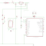
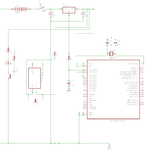
any problems with these circuits?for sensor part,i couldn't get the desire waveform(square wave),i need to modulate the signal to 38khz and then emit(IR),then tssp4p38 will receive it,do i still need any amplifier?i had connected this sensor part to breadboard and i get some useless wave(is like some kind of big noise wave).The mcu i used is pic16f877a.
this is the program i used to generate the 38khz:
Code:
#include <pic.h>
#define _XTAL_FREQ  20000000
#define _FOSC_RC & _WDTE_OFF & _PWRTE_OFF & _BOREN_ON & _LVP_OFF & _CPD_OFF & _WRT_OFF & _CP_OFF 
 
//Prescaler 1:1; PR2 Preload = 131; Actual Interrupt Time : 26.3 us
 

void init(void)
{

	TRISB	= 0X00;
	TRISD= 0X00;
	TRISC= 0X00; 	//configure Rc2 as output for Emitter(pwm)
	CCP1CON = 0X0C;     //select PWM mode.
   	PR2 = 131;      //Set period register for approx. 38khz.
  	T2CON= 0X04;     //Set timer2 pre/post scalers to 0 & start Timer2.

}


void main()
{

     init( );
	while(1){
	 CCPR1L =  0;
	__delay_ms(500);
     CCPR1L = 65; //Set duty cycle for approx 50%
    __delay_ms(100);
	 		}		  	
 }
i'm using hi-tech universal toolsuite(MPLAB).

for apr9600 voice chip,i had soldered to the copper strip board and when connect to power supply,it no response at all...is that circuit correct?

the photo is the 1 i had soldered.

this is the datasheet of emitter >>> https://elcodis.com/parts/766705/TSAL6200.html
this is the datasheet of receiver>>> https://www.vishay.com/docs/82474/tssp4p38.pdf

the attached pdf is the datasheet of apr9600,i had used random access mode.
 

Attachments

  • may30-apr.png
    may30-apr.png
    22 KB · Views: 100
  • sensor part with transistor.png
    sensor part with transistor.png
    22.1 KB · Views: 98
  • APR9600.pdf
    2.1 MB · Views: 90
  • IMG_1894[1].JPG
    IMG_1894[1].JPG
    2.7 MB · Views: 94
  • IMG_1893[1].JPG
    IMG_1893[1].JPG
    2.7 MB · Views: 91
Last edited by a moderator:

Re: circuit related questions

What is the source of IR, and measure the 38Khz of source for sure....

- - - Updated - - -

you need not to demodulate in receptions u can just use the Envelope signal in the output....
 

How?what you mean the source?the demodulator is built in with the receiver already right?
 

Source of IR means how are you providing 38 KHz signal to IR module?

i'm using software to generate 38khz frequency and then feed the signal to IR emitter. Correct?

right.. The voltage input given to IR led is the source that must be modulated in 38Khz..

the voltage input given to IR led is 5v but the operating voltage is 1.6v,so, if i use voltage divider circuit associated with 2n2222a transistor,is that ok?
 

show the schematic of IR transmitter(emitter), which led is IR one..

If it is LED1 and LED2 in APR module. They wont glow or emit at all, because you connected 100k in series...
 

the 2nd schematic attached is the sensor part. the 1st schematic is apr9600 part.
 

the LED 1 is the IR LED,which connected to a 68ohm resistor,the transistor base are connected with a 3.3k ohm resistor.
 

Attachments

  • sensor part with transistor.png
    sensor part with transistor.png
    22.1 KB · Views: 100

You are now trying to check weather IR receiver works or not with the input from MC and output to a CRO.

make sure that the receiver outpur is connected with RD0 or not...

You configured RD0 as output not input....
 

now,i only tried the sensor part,without connecting to mcu, i connected the output of receiver to oscilloscope and ground of the receiver and oscilloscope to ground as well and i get some stupid wave =.="

the only part i connected to mcu is the anode of IR emitter, which i use software modulated method to generate 38khz.
 

38khz pin mean the output pin of mcu which i connect to the emitter anode? the problem is,i should get some square wave from output of receiver which connected to oscilloscope right? but i'm getting only noise wave(some noise sine wave)....if i check output of receiver with multimeter,what should i get?
 

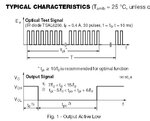
Give the output of the MC to cro and check for 38khz. if you are giving and the IR led is glowing means the output of receiver should be 0V (0.7V noise is acceptable) if you disconnect the led means output should be nearly 4 to 5Vreceiver.JPG. I think its works for you...... you are confused with small noise voltage (viewing it as a big one)..
 
Last edited:

Give the output of the MC to cro and check for 38khz. if you are giving and the IR led is glowing means the output of receiver should be 0V (0.7V noise is acceptable) if you disconnect the led means output should be nearly 4 to 5VView attachment 93116. I think its works for you...... you are confused with small noise voltage (viewing it as a big one)..

you said this "if you are giving and the IR led is glowing means the output of receiver should be 0V "

giving what? i think i measured the receiver is 5v when IR led glowing...
 

look at the timing diagram and think.......

- - - Updated - - -

If you are giving 38khz signal to the IR led means it will glow and you will get a low output in reception (Active low)

- - - Updated - - -

If you are giving NO signal to the IR led means it wont glow and you will get a high (5V) output in reception (Active low)
 

i know this,but what i'm saying is,i get some kind of sine wave of the receiver output pin, according to you, i should get some square wave right since it is pulse at 38khz..
 

you shouldnt get square wave you should get nearly zero volt (0 to 0.7V)

- - - Updated - - -

Dont worry about that waveform check the voltage with multimeter.
 

ok i will check and tell you tomorrow.

besides, if i want to measure distance,how to do that? i thought can count the pulse receive and hence justify the distance for example in 1.5m received pulse in 120ms is 50; 1m received pulse in 120ms is 30...but it is active low....so how can i do it?
 

Status
Not open for further replies.

Similar threads

Part and Inventory Search

Welcome to EDABoard.com

Sponsor

Back
Top