Continue to Site

Welcome to EDAboard.com

Welcome to our site! EDAboard.com is an international Electronics Discussion Forum focused on EDA software, circuits, schematics, books, theory, papers, asic, pld, 8051, DSP, Network, RF, Analog Design, PCB, Service Manuals... and a whole lot more! To participate you need to register. Registration is free. Click here to register now.

Microcontroller based automatic transfer switch

Status
Not open for further replies.

Asabzi2000

Junior Member level 1
Joined
Mar 13, 2013
Messages
19
Helped
0
Reputation
0
Reaction score
0
Trophy points
1,281
Location
Tarkwa, Ghana
Visit site
Activity points
1,422
I am designing a an automatic transfer switch with a microcontroller as the main control element. The controller would receive analog inputs from AC sensors and based on their states, switch on a generator set or allow the system to run on normal utility supply. The controller will start the gen set engine through solid state relays. Should I use an AC current sensor or AC voltage sensor? How do I configure the sensor so they can be detected by the MCU. What kind of SSRs may be appropriate? Please suggest!
 

I am designing a an automatic transfer switch with a microcontroller as the main control element. The controller would receive analog inputs from AC sensors and based on their states, switch on a generator set or allow the system to run on normal utility supply. The controller will start the gen set engine through solid state relays. Should I use an AC current sensor or AC voltage sensor? How do I configure the sensor so they can be detected by the MCU. What kind of SSRs may be appropriate? Please suggest!

For sensing mains power outage you can use optocoupler resistor 47K and one diode. This have easy design and its isolated.

Optocoupler Mains Power Sense.jpg

You can SSR for starting generator, I supose generator starter, but I dont see purpose of that, you can use standard relay or contactor for that purpose.

:wink:
 

Thanx tpetar, but could u help me with sample schematic. Am using solid state relays in place of electromechanical relays. By virtue of their advantages over EMRs. Am doing the design in Proteus.

- - - Updated - - -

Thanx tpetar, but could u help me with sample schematic. Am using solid state relays in place of electromechanical relays. By virtue of their advantages over EMRs. Am doing the design in Proteus.
 

Thanx tpetar, but could u help me with sample schematic. Am using solid state relays in place of electromechanical relays. By virtue of their advantages over EMRs. Am doing the design in Proteus.

Its ok solid state no problem, you already know that you need to provide adequate heatsink and additional parts, also you already know that SSR have power dissipation and develops additional heat.

I also love to use SSR but not always.

:wink:
 

Thanx, I tried it but the output at the opto pin 5 is not stable. I used 240V and 50Hz. How do I interface it to my MCU? Its PIC16F877.
 

Thanx tpetar, but could u help me with sample schematic. Am using solid state relays in place of electromechanical relays. By virtue of their advantages over EMRs. Am doing the design in Proteus.

SSR example circuit, I suggest isolated triacs such as BTA serie :

schematic.gif

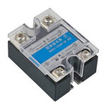
Or you can buy or get SSR module, but check to be isolated :

solid-state-relay-SSR-02.jpg
 

Thanx once more! But I guess the trigger on the MOC3021 input is the pulse receiced from the microcontroller? right!

- - - Updated - - -

The optoiso gives a an oscillating output between 0-5V. Do I just connect it to the MCUs ADC? Should frequency have an influence?
 

Hello! am trying to connect three optoisolators as voltage sensors to a PIC16F877 MCU. I've built the optoiso circuit with 47k resistor and 1 diode. The output of the optoiso oscillates between 0-5V. How do I interface it to the PIC16F877. Do I just connect it to the MCU's ADC pins? Urgent help needed. Thanx in anticipation!
 

What do you want - to detect the presence of AC or AC output of range? If the presence of the AC - check the pulse of the digital input MCU, such as an interruption. If being in a band, you need to change the schema of the sensor.
 

Thanx Pplus, I want to detect the presence of AC, but how do I check the digital input to the MCU? Am quite new to MCUs. But I want to connect 3 voltage sensors to the MCU, one to the normal utility, one to the generator and one to the load; so that when utility is lost, the MCU will start a genset engine through a solid state relay. When the gen develops voltage, the gen sensor will communicate it to the MCU and finally the MCU actuates a stepper motor on whose shaft is a circuit breaker actuator. The actuator switches the supply. All this will be factored into the MCUs firmware.

- - - Updated - - -

Thanx Pplus, I want to detect the presence of AC, but how do I check the digital input to the MCU? Am quite new to MCUs. But I want to connect 3 voltage sensors to the MCU, one to the normal utility, one to the generator and one to the load; so that when utility is lost, the MCU will start a genset engine through a solid state relay. When the gen develops voltage, the gen sensor will communicate it to the MCU and finally the MCU actuates a stepper motor on whose shaft is a circuit breaker actuator. The actuator switches the supply. All this will be factored into the MCUs firmware.
 

Sensor.pngSensorWawe.png
Describe the temporal characteristics. What time should pass from a loss of power before switching. I think this sensor is suitable.
 
Thnx Pplus, pls is my circuit connection OK? How do I describe the temporal characteristics? Averagely I want about 10 seconds to elapse on power loss b4 switching. I've seen ur circuit. Pls explain it more for me.

- - - Updated - - -

Hi Tpetar, your assistance has been superb so far. But kindly assist me further, how do I configure the MCU to sense the analog inputs. Am using Proteus design suit an mikroC. This is the design so far. Kindly help!
 

Attachments

  • MBATS.GIF
    MBATS.GIF
    144.7 KB · Views: 160

To start a generator, you have to apply LV to the fuel cut off valve* and crank the engine over with a 200A, 12 or 24V battery, so i don;t think a solid stae switch is going to improve the reliability of any thing. There are two thresholds you need to attend to :- Starting the generator, say when the mains has been low for 3 seconds and then changing over to it after another 5 seconds to allow the generator to start and get up to its rated voltage. Likewise when the mains has returned, leaving the generator on load for ten seconds, before changing back to the mains, then an additional 2 to 3 minutes for the generator to run off load to cool it down before cutting of the fuel.
* if you have an electrical fuel pump it should come on now. Beware Diesel generators with mechanical fuel pumps need a lot of cranking. You could have a timer that in the event of the engine not starting within 20 seconds of cranking, it shuts the cranking off - there is nothing more to be gained other then a burn't out starter and a flat battery.
Frank
 
Thanks a lot Chuckey, but coul u help me with a schematic. How do you see my connection of the voltage sensor and the MCU in the circuit?
 

Status
Not open for further replies.

Similar threads

Part and Inventory Search

Welcome to EDABoard.com

Sponsor

Back
Top