Continue to Site

Welcome to EDAboard.com

Welcome to our site! EDAboard.com is an international Electronics Discussion Forum focused on EDA software, circuits, schematics, books, theory, papers, asic, pld, 8051, DSP, Network, RF, Analog Design, PCB, Service Manuals... and a whole lot more! To participate you need to register. Registration is free. Click here to register now.

DC-DC converter urgent help

Status
Not open for further replies.

ahmedmedowahdan

Member level 1
Member level 1
Joined
Jan 30, 2013
Messages
38
Helped
0
Reputation
0
Reaction score
0
Trophy points
1,286
Activity points
1,463
i have acompetition within 1 week and i have alot of problem with my desing

i want :

dc-dc converter 48 to 24 or 12
please suggest me all requirement
i want to use IRF9540n p-channle
and i want to make feedback using AVR microcontroller
 

You have not mentioned your current/power requirement. Nor much other parameters, either - such as isolated/not isolated and if not isolated, if the most negative wire in input os "ground" and common to the output, or if you have some more unusual needs. Without more info it is hard to guide you to viable solutions.

The most basic and simplest configuration would be so-called "buck" regulator, a.k.a. step-down topology. There are plenty chips intended for such converters, so one usually builds around such a dedicated controller chip.

However, I wonder why you want to use a P-channel MOSFet and especially AVR for a basic step-down controller? Well - P-FET may be handy as the switch, but using a microcontroller definitely is a challenging proposal.

microcontroller is for generating pwm and feedback to it to adjust pwm duty cycle
rating : 48 in - 24/12 out
24 volt 10A
12 volt 12A
i can use n-mosfet if it is better
for isolation i think there is no time for it ( if it's easy to implement tell me about it)
 

Well, let's forget the isolation, as it makes things always more complicated. Also, using P-FET is OK, and actually a bit easier to control when you want a micro-controller to do the job.

I assume you know the calculations for a buck regulator: Finding inductance and calculating currents etc. If not, you better to learn - maybe first looking at articles you can locate by Google. (One pretty good document from Texas Instruments: https://www.ti.com/general/docs/lit/getliterature.tsp?baseLiteratureNumber=slva477)

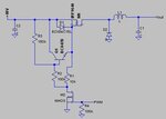
I sketched a circuit for switch based on P-MOS and need for micro-controller compatible driving. It is just a principle draft, and component values are only indications of magnitude.You should check them yourself. Some hints: M1 should be your choice, such as IRF9540N. M2is a small-signal FET, whose gate drive is compatible with your processor, and which can handle the input voltage (>50V). Zener D1 protects the gate for overvoltage, Q1 helps discharging the gate to speed up the circuitry. C1, C2, L1 and D2 you select according to your calculations for a buck converter.

Again, this sketch is totally untested, scribbled in 5 minutes, and is not even simulated. The values presented are "first guess" values, and need to be properly calculated. So the warranty time is <1 us :razz:

17545_22.jpg

Good luck!
 
Last edited:

Well, let's forget the isolation, as it makes things always more complicated. Also, using P-FET is OK, and actually a bit easier to control when you want a micro-controller to do the job.

I assume you know the calculations for a buck regulator: Finding inductance and calculating currents etc. If not, you better to learn - maybe first looking at articles you can locate by Google. (One pretty good document from Texas Instruments: https://www.ti.com/general/docs/lit/getliterature.tsp?baseLiteratureNumber=slva477)

I sketched a circuit for switch based on P-MOS and need for micro-controller compatible driving. It is just a principle draft, and component values are only indications of magnitude.You should check them yourself. Some hints: M1 should be your choice, such as IRF9540N. M2is a small-signal FET, whose gate drive is compatible with your processor, and which can handle the input voltage (>50V). Zener D1 protects the gate for overvoltage, Q1 helps discharging the gate to speed up the circuitry. C1, C2, L1 and D2 you select according to your calculations for a buck converter.

Again, this sketch is totally untested, scribbled in 5 minutes, and is not even simulated. The values presented are "first guess" values, and need to be properly calculated. So the warranty time is <1 us :razz:

View attachment 86506

Good luck!
thanks alot for your help, but h have some questions:
1- Zener is connected between gate and 48 volt is that true?
2- i read that gate need enough current to be fully on fast , do you think that BC847B will provide enough current?
3- why R4?and R1?
 

Hi,
Some answers to your questions:
1. Yes zener is connected between +48 V and gate. Note, that +48V is also MOSFETs source, to which the gate is referenced. NOTE: Unfortunately in my original drawing the zener was wrong way! Purpose of this zener is to protect the gate from excessive voltage.
2. The gate appears much like a quite large capacitor had been connected from it to source. For IRF9540 that capacitance is about 1300 pF. You are right, to charge that capacitor fast enough needs some serious current. As the threshold voltage, on which transistor is fully on, is only about 2...4V, we are interested mainly in speed of transition between 0 and 4V. Because BC847 can provide easily up to 100 mA, it should be good enough for discharging the gate - that is its role here. The OFF->ON drive is provided by M2, and applied through R1!
3. So R1 switches the switch on, and R2/Q1 helps to switch it off.
R1 limits drive to acceptable value, and I believe in my original schematics the resistors are all bit big for good results, as I had not calculated them carefully. R4 keeps the switch off while micro-controller's pin connected to it is floating (e.g. while program is not yet active, or in reset state etc.). That is important to consider!

I have attached a new draft schematics - still I have had no time for proper simulation - which btw. would require some value for instance for the switching frequency. I have drawn it with LTSPICE -a nice and simple to use program from Linear Technology. ( www.linear.com/designtools/software )

In this version the resistors are smaller for improved speed and there is also a capacitor C3 to speed up switching ON. added resistor R5 should secure, that the gate charge is falling lower even after Q1 "gives up" of more forcefully emptying the gate charge.

By adding +48V DC source generator + a PWM pulse train generator + a suitable resistor for loading the output, and running simulations, one should be able to easily tweak the component values closer to optimum values. Of course, now undefined input and output capacitors and the inductor must have values, too - but one has to know the switching frequency to make any intelligent initial guesstimate there.

14920_32.jpg

The source file for LTSpice is also in an attachment.

- - - Updated - - -
 

Attachments

  • Draft3.rar
    725 bytes · Views: 114

hi,
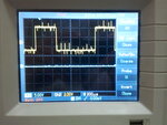
this my pwm image ,it's 100 khz , is it normal? it has alot of noise
Photo0072.jpg
 

please suggest me suitable inductor from digikey or rs component

Lmin=150 uh
max current =10 A


Status
Not open for further replies.

Part and Inventory Search

Welcome to EDABoard.com

Sponsor

Back
Top