Continue to Site

Welcome to EDAboard.com

Welcome to our site! EDAboard.com is an international Electronics Discussion Forum focused on EDA software, circuits, schematics, books, theory, papers, asic, pld, 8051, DSP, Network, RF, Analog Design, PCB, Service Manuals... and a whole lot more! To participate you need to register. Registration is free. Click here to register now.

how to choose the charge pump current in PLL circuit design

Status
Not open for further replies.

rf1008

Full Member level 2
Full Member level 2
Joined
Mar 30, 2012
Messages
129
Helped
7
Reputation
14
Reaction score
7
Trophy points
1,298
Visit site
Activity points
2,219
Hello,

I use one PLL chip from ADI in my design and have a question on the charge pump current. Several current levels could be selected, from lower 0.6mA to higher 5mA. I verified and found that lower current will decrease the noise out-of band which seems to be better,I haven't found any performance deteriorated maybe due to my incompleted measurement.

Would you pls advise how to choose the charge pump current ,the lower the better or....thanks.
 

I guess it is a bandwidth thing. If you want a big bandwidth in the control loop, you want the highest output current. If you do not want a big control loop bandwidth, a lower current could be used. Bigger current should give you less susceptability to stray noise pickup. Battery operation--you would go with the low output current setting.
 

Thanks, you mean the bandwidth of loop filter, is it only decided by the loop filter itself design?
 

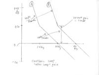
Yes, changing the current output from .5 to 5 mA is like putting an amplifier with a gain of 10 in the control loop filter. If you keep the other component values the same, you will get a bigger control loop bandwith with the 5 mA setting (~10x the bandwidth--see sketch of open loop gain change)


Attachments

  • control loop gain.jpg
    control loop gain.jpg
    119.9 KB · Views: 171
Last edited:

Changing the charge pump current will increase the bandwidth of the open loop response, but the affect on closed loop response is not so straightforward. A larger open loop gain may cause instability or excessive overshoot if the phase response is not also considered.
 

that is only true if there is some parasitic reactance in the load (like a big bypass capacitor to ground on a VCO tune line). For a VCO with not much parasitics, If you move the poles and zeros up in frequency (like in the sketch) there is NO impact on ringing/stability.
 

Right, you have to scale your compensation poles and zeros as well, which must be done by changing component values. Your sketch shows a zero actually being shifted in frequency, which does not happen as a result of changing charge pump current.
 

Sorry, sometimes I am not as clear as I intend to be. You are right, if you just up the gain without changing the Rs and Cs, you can make the loop unstable. You can do a little of a gain change and get away with it though.
 

Status
Not open for further replies.

Part and Inventory Search

Welcome to EDABoard.com

Sponsor

Back
Top