Continue to Site

Welcome to EDAboard.com

Welcome to our site! EDAboard.com is an international Electronics Discussion Forum focused on EDA software, circuits, schematics, books, theory, papers, asic, pld, 8051, DSP, Network, RF, Analog Design, PCB, Service Manuals... and a whole lot more! To participate you need to register. Registration is free. Click here to register now.

16 Pins LCD In Proteus

Status
Not open for further replies.

shan_ahmed

Newbie level 4
Newbie level 4
Joined
Sep 24, 2012
Messages
7
Helped
0
Reputation
0
Reaction score
0
Trophy points
1,281
Activity points
1,347
Hello everyone, i want a 16 pins lcd in proteus, where to slect it? model nmbr?? Please
 

LM016L Display 16x2(Component mode or press p key in keyboard)
 

I want 16x2 LCD having 16 pins, LM016L has 14 pins :cry:

- - - Updated - - -

I've got this circuit and i want to run it on proteus, Image below
 

16x2 lcd display circuit
 

Attachments

  • untitled.bmp
    2.3 MB · Views: 264

I've uploaded the circuit wich i want to stimulate on proteus..
In the circuit there is a LCD having 16 pins, but LM016L has 14 pins, please help..
How can i design this circuit on proteus??
 

That circuit wouldn't work in real life (at least not reliably). I doubt anyone ever implemented it for real.
It is missing capacitors on the oscillator pins so the microcontroller probably never executed a single instruction.
It's also missing any decoupling. Also, the supply rail looks like it
doesn't connect to the transistor collector points (badly drawn circuit). Reset circuit components are sized
inappropriately (no reason to use an expensive 10uF 63V capacitor).
Conclusion: just because it's on the internet doesn't mean it's a good circuit to copy.
 

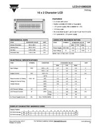
It says its a 16x2 LCD, LCD-016m002B, i've also attached it's data sheet..

I've got its code to0o..
May b e it helps. code...


Code C - [expand]
1
2
3
4
5
6
7
8
9
10
11
12
13
14
15
16
17
18
19
20
21
22
23
24
25
26
27
28
29
30
31
32
33
34
35
36
37
38
39
40
41
42
43
44
45
46
47
48
49
50
51
52
53
54
55
56
57
58
59
60
61
62
63
64
65
66
67
68
69
70
71
72
73
74
75
76
77
78
79
80
81
82
83
84
85
86
87
88
89
90
91
92
93
94
95
96
97
// Program to make a Liquid level indicator using LCD
#include<reg51.h>
sbit rs=P1^0; //register select pin
sbit rw=P1^1; //read/write pin
sbit e=P1^2; //enable pin
sbit quat=P3^0; //pin connected to quater level of tank
sbit half=P3^1; //pin connected to half level of tank
sbit quat_3=P3^2; //pin connected to three -fourth level of tank
sbit full=P3^3; //pin connected to full level of tank
sbit spkr_on=P3^4;  
sbit spkr_off=P3^5; // pin to off speaker
 
void delay(int k) //delay function
{
int i,j;
for(i=0;i<k;i++)
  for(j=0;j<1275;j++);
}
 
void write(int j) //write function
{
rs=1;  //selecting command register
rw=0;  //selecting to write
P2=j;  //putting value on the pins
e=1;  //strobe the enable pin
delay(1);
e=0;
return;
}
 
void cmd(int j)  //command function
{
P2=j;  //put the value on pins
rs=0;  //selecting command register
rw=0;  //selecting to write
e=1;  //strobe enable pin
delay(1);
e=0;
return;
}
 
void puts(char *a) //puts function to print a string
{
unsigned int p=0;
for(;a[p]!=0;p++)
write(a[p]);
}
 
void lcd_init(void) // function to initialise the LCD
{
cmd(0x38); //setting 8-bit interface, 2 lines, 5*7 Pixels
delay(1);
cmd(0x0e); //turning on underline visible cursor
delay(1);     
cmd(0x01); //clearing screen
cmd(0x80); //moving cursor to the begining of line 1 of LCD
}
 
void main()
{
quat=half=quat_3=full=spkr_off=1; //configuring as input pins
quat=half=quat_3=full=spkr_off=0; //lowering input pins
spkr_on=1;    // making speaker on pin high,as it works on negative logic
while(1)
{
  while(quat==0&&half==0&&quat_3==0&&full==0&&spkr_off==0)   //condition when tank is empty
  {
   lcd_init();        // initialising LCD
   puts("VACANT");       //printing VACANT on lcd
  }
  while(quat==1&&half==0&&quat_3==0&&full==0&&spkr_off==0)  //condition when tank is quater
  {
   lcd_init();
   puts("QUATER");      //printing QUATER on lcd
  }
  while(quat==1&&half==1&&quat_3==0&&full==0&&spkr_off==0)  //condition when tank is half
  {
   lcd_init();     
   puts("HALF");      //printing HALF on lcd
  }
  while(quat==1&&half==1&&quat_3==1&&full==0&&spkr_off==0)  //condition when tank is three-fourth
  {
   lcd_init();
   puts("3/4 FULL");     //printing 3/4 FULL on lcd
  }
  while(quat==1&&half==1&&quat_3==1&&full==1&&spkr_off==0)  //condition when tank is full
  {
   lcd_init();
   puts("FULL;CLOSE TAP");     //printing FULL;CLOSE TAP on lcd
   spkr_on=0;// Enabling speaker
  }
  while(quat==1&&half==1&&quat_3==1&&full==1&&spkr_on==0&&spkr_off==1)//enabling high speaker_off pin
  {
   spkr_on=1;//disabling speaker
  }
}
}

 
Last edited by a moderator:

...and what a surprise, the code is as bad as the circuit.
It constantly loops the LCD initialize routine and repeatedly prints the same text.
 

How to do that?? wot to do with remaining 2 pins??

If the LCD is HD44780 compatible the remaining two pins are for a backlight, pins 15 and 16 in the schematic you'll uploaded, which are certainly not a requirement for a successful simulation.

Simply leave them disconnected.


BigDog
 
If the LCD is HD44780 compatible the remaining two pins are for a backlight, pins 15 and 16 in the schematic you'll uploaded, which are certainly not a requirement for a successful simulation.

Simply leave them disconnected.


BigDog

Sorry bro im a beginner, how to know if it is HD44780 compatible??? ::sad:
And which pins should remain disconnected?? i've uploaded the cicuit-diagram to0o, can u give it a look and tell me??
And data sheet of LCD is also uploaded..
 

As I've indicated in my previous post, pins 15 and 16 of the LCD in the schematic you've posted in reply #3 are for a backlight which are not necessary.

Therefore a 14-pin LCD model which uses an HD44780 compatible controller should work fine for your simulation.

The LCD you've selected utilizes a KS0066 controller which I believe is compatible with the HD44780 controller.

You need to study the datasheet of the LCD to ensure the proper pinout as they vary from one vendor to another.

Don't assume they are in the same order as the schematic you've posted.


BigDog
 
If your LCD uses KS0066 as the datasheet you have uploaded in post #7 then it is HD44780 compatible.
 
Thankeuuuuuuuuuu Jestin...It really helped me :)
I've another problem with microcontroller 89c51, it has no 20th and 40th pin in proteus.. w0t shud i do0 now..??

- - - Updated - - -

16 pin LCD 16 pin Proteus design file and PCB footprint


more PCB Footprints:
https://www.edaboard.com/threads/257982/

Hey i cant connect wires with this LCD :-( Just now i tried, it is of no use, :-(
 

As 20th and 40th pin are Gnd and Vcc. It is internally connected in proteus.
 

Status
Not open for further replies.

Similar threads

Part and Inventory Search

Welcome to EDABoard.com

Sponsor

Back
Top