Continue to Site

Welcome to EDAboard.com

Welcome to our site! EDAboard.com is an international Electronics Discussion Forum focused on EDA software, circuits, schematics, books, theory, papers, asic, pld, 8051, DSP, Network, RF, Analog Design, PCB, Service Manuals... and a whole lot more! To participate you need to register. Registration is free. Click here to register now.

DTMF signal ,maybe processing

Status
Not open for further replies.

newbie noob

Newbie level 5
Newbie level 5
Joined
Jul 10, 2012
Messages
10
Helped
0
Reputation
0
Reaction score
0
Trophy points
1,281
Location
Damascus
Activity points
1,379
DTMF signal ,maybe processing , please help x(

Hello edaboard
recently I have been working on a remote automating system , building a circuit to recieve a dtmf signal from the telephone line and then do its job
but I am facing some problems . CM8870 is the circuit I used ,

**broken link removed**
that would be the magnetic isolation a guy proposed (the first diagram) I did the very same circuit but with 6.2 zeners not 5.2v.
1st) the circuit is decoding only some of the numbers .
2nd) the circuit is not working at all when connecting the ADSL Router line .
3rd) the circuit is not working at all when the dtmf signal is being sent by a different telephone line ,(like when someone calls the circuit answers but it doesnt respond to the dtmf he is sending)

thanks in advance
please help
 
Last edited:

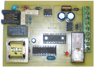
Use this checked and working like a charm projects :

With 1 Relay and 1 Sensor Version
https://www.elektronika.ba/507/telefonski-kontroler-v1/

c_507_phonecontroller_pic.jpg


shema1.png


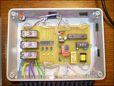
With 6 Relays and 6 Sensors Version
https://www.elektronika.ba/508/telefonski-kontroler-v2/

c_508_plc_v2_pic1.jpg


shema3.png
 
Last edited:

Use this checked and working like a charm projects :

With 1 Relay and 1 Sensor Version
https://www.elektronika.ba/507/telefonski-kontroler-v1/

c_507_phonecontroller_pic.jpg


View attachment 77184


With 6 Relays and 6 Sensors Version
https://www.elektronika.ba/508/telefonski-kontroler-v2/

c_508_plc_v2_pic1.jpg


View attachment 77185
I am gonna try that , thank you Mr.Tpetar !
I hope that works , but I notice that this circuit is the same as the one I used but with a little more amendment .
if you may have the time to answer my following questions ...
are you responding to my post in respect to my problems ? or your giving me a circuit that your sure it will works ? cause I used a circuit that someone was sure that it works but it didn't , I guess the problem is with the telephone line here in my country , could it be any chance that the lines in here are weak and need a little more signal processing and clearing so the dtmf decoder works ?
how would replacing those component would make it avoid the adsl noise and make it catch a remotely sent dtmf ? sorry if your not getting with me for my bad English , or if I am miss leading you
By the way I am avoiding using a micro controller , although it will make it less secure and more ...
and can you tell me what the 220nf capacitor and the 0.1 mf works for ?
thanks for your time ...
 

This works, dont worry I try this and working like a charm.

I found one mistake in circuit for 1 Relay control.

On PCB "plocica_bot.gif" resistor 10K and capacitor 0,1uF should swap places.

Also I must change 10K with 6,8K resistor on input of 8870 IC , I get very low sound and low level sound DTMF. With lowering resistor value I get DTMF more stronger. If you have similar problem do the same or put even lower 4,7K resistor.

I use small isolation telephone line isolation transformer from some old modem, and I made some redesign of PCB for other type and shape of relay. This trafo impedance should be 1:1 600R:600R impedance, because telephone line have 600R impedance, in US & Canada they have I think 900R but not sure for them.

All of this like devices must be installed after ADSL filter, NOT before ADSL filter.

This device in both versions have password to access device.

To make this to work well you must program and configure uC.

560R have rule to reduce load on line if output is connected to very low impedance. You can use also 620R resistor.

Non polarised capacitor is placed in serie with transformer line to prevent DC current from flowing in the transformer winding which may prevent the line from returning to the on-hook state. Use at least 400V voltage ratings.

Varistor on line input VDR 500V, can be omitted. Also you can get this varistor from almost any good quality PC modem.

On 4N35 optocoupler you can sense anything what you whant, 220V is just given like example to see if device is turned on or off (on power). You can sense lower voltages just adjust resistor and exclude diode if is DC current.

You can use solid state relays instead coil relay, or you can use small relays to switching contactors which controls some three phase or single phase central heating oven or something else powerful.

In SMD variant this complete device can be very small.

File "plc.lay" is PCB made with sPrint-Layout software.

:wink:


According to your posted parts of circuit which you try, and you say didnt work do the following :

Replace 220nF/400V with 100nF/400V and must be non polarised capacitor.
Lower resistor value of 100K of 8870 input to 10K/6,8K/5,1K/4,7K.
Check isolation transformer that is 1:1 600R:600R impedance.
Do you did well programming of uC?
uC is working-good and without damages?
On your posted circuit quartz dont have needed capacitors of 22pF connected to ground!


I think you get enough information to start making this project.

After this you can go to SMS remote sensing and control.

:wink:
 
Last edited:

Oh my *** , you are just a helping man ! those info were almost perfect ! thanks a lot , I cracked up an old modem harvested the transformer and replaced the one on the circuit and there was so much different , the circuit works much better now , it recognizes all the Tones BUT , it didn't respond to the dtmfs being sent remotely from other telephone lines ... which is the whole point ,
I didn't place that varistor yet (if you please tell me what it does ? ) and didn't even grounded the QUARTZ nor replaced the 220nf yet , but but I replaced the 100k resistor with a 4.7 k , does all of this causing the circuit not to respond remotely ? or which of them ? well I guess only the varistor is the problem , so I am going to buy one now ...
again thanks for your respond , and thanks in advance if you respond again...

Manar,. Syria Damascus ( Same as Serbia before a couple of decades)
 

No, varistor is just surge protection.

See additional info about that:
https://www.epanorama.net/documents/surge/telesurge.html


This circuits what I post works 100% guaranteed!

I have not seen your complete circuit, maybe there is some errors.
Maybe you make some mistake when soldering,...

You must read description file first how this devices works, and what you must to do to configure settings.

"The administrator should call-in the device from another telephone. After a few (configurable amount of) rings, the controller will pick-up the line and answer with a beep. After the beep the administrator must enter 4-digit password onto the keypad of his phone (DTMF). This must be done in 6 seconds. If the password is not entered in 6 seconds or wrong password has been entered, the device will beep and hang up. You can call it again now."


This device is designed to work like was described in description file. In other words he is designed to receive calls from another phone line or mobile. If you have problems in pickup call check small relay, trafo, and whole input section. Check 4N35 section!
 
Last edited:

Ok I see what you mean , but let me make a notice that as I said before I am not including any Micro controller to the circuit , the system is gonna be none secured , no password needed , I am planing to make the administrator turn on only one relay by pressing for example a tone , I haven't considered making the circuit answer the phone yet , but the problem here is that when examining the decoding part ( only the decoding part) the 8870 is not responding to any dtmf tones being sent from elsewhere than the local telephone , got me ?
would it help if i post a diagram or something ?
 

Status
Not open for further replies.

Part and Inventory Search

Welcome to EDABoard.com

Sponsor

Back
Top