Continue to Site

Welcome to EDAboard.com

Welcome to our site! EDAboard.com is an international Electronics Discussion Forum focused on EDA software, circuits, schematics, books, theory, papers, asic, pld, 8051, DSP, Network, RF, Analog Design, PCB, Service Manuals... and a whole lot more! To participate you need to register. Registration is free. Click here to register now.

Op-Amp does not respond to current transducer LEM LA55-P

Status
Not open for further replies.

topes

Newbie level 4
Newbie level 4
Joined
Jun 29, 2012
Messages
7
Helped
0
Reputation
0
Reaction score
0
Trophy points
1,281
Activity points
1,343
Hello,

I'm new to this forum and it has been almost 9 yrs since I last work on electronic projects.
I need some help in solving my current monitoring circuit for a fuel-cell system.

The circuit is attached. I use LEM LA55-P current transducer to monitor 0-20A of DC current.
I use 741 opamp to convert the reading to a 0-10V analog to be fed to a PLC.

The voltage across the 100ohm resistor shows relative changes ranging from 0-2V for primary current of 0-20A.
But, the op-amp 741 output doesn't respond to that. The output maintains at a certain volt.
I tried regulating the 4kohm resistor to reduce the gain, eventhough the opamp output volt changes, but still it maintains static.
I've also replaced the 741, but same issue.

Can anyone please assist me in this.

Thanks.
 

Attachments

  • LEM_LA55P OPAMP.pdf
    30.6 KB · Views: 247
  • LEM_LA55-P.pdf
    72.4 KB · Views: 200

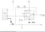
You have connected transducer wrong. On the circuit should be +15V, -15V and common point.
It should look like that Capture.JPG
 
Oh ok, I thought that it doesn't matter to have the -ve side.
How does that affect the opamp, eventhough the LA55P produces output?

BTW, can you advise me a device/circuit or an ic to generate the -ve supply.
I did some reading just now, can I use MAX1044, or any equivalent substitute.
I use LM7815 regulator to generate the 15Vdc.

Anyway, thanks for your prompt reply.
 

UA741 is not rail-to-rail input/output. In datasheet is written that input voltage rang is +/- 13V if you supply amplifiers by +/-15V.
About how to get -15V. MAX1044 is not fit to you. Current must be more than 50mA. You can use already prepared DC/DC converter ( use AM2D-1515 ) or create himself (one of the most easiest circuit is based on MC33063). I suggest you take AM2D-1515 . Firstly it will take less time, secondly it will more easy to implement and take the same place ( even possible it will be more compact). Drawback is price and 100 KHz noise (you can reduce it by useing output LC filter)
 

The more I do, then the more I realize I dont know. But I like it.
And it becoming hard suddenly. I'm not sure if the parts available immediately.

I am still confused though, because I built another amp circuit, this one to measure the voltage. Still a non-inverting with 741.
But it still works without -10V at the V-. The Voltage monitored is ranging 0-50Vdc, step it to down to 0-5V (v-divider), and double amplify it with 741. It works fine.

And does the LA55P need -15V eventhough I only measure continuous DC current?

I'm thinking of solving this by changing the LA55P itself or the 741, to maybe another type, if available.

I hope of your guidance throughout this. Thanks.
 

If you want use unipolar voltage that following must be taken into account:

1. The supply voltage should be equal to the sum of the positive and negative voltages indicated in the datasheet (e.g. a ±15 V product should be powered with +30 V).
2. Selection of the measurement resistance and the maximum current must not imply excessive power dissipation in the transducer output stage (do not hesitate to contact LEM to get the correct measuring resistance assessment).
3. The output stage is designed for use with a bipolar power supply and diodes must be inserted in series with the output (see the drawing below) to allow a minimum output bias voltage without creating a measurement offset.

You could read about unipolar connection at the link: **broken link removed**

What precision should be your measurement?
 
Ah, thats good. Thanks for the good news.
The in voltage range is around +-12-15. I do have 24v supply in the main circuit and can be used in this case, i guess. So the opamp 741 also be unipolar at +10v.

I dont need it to be so precise. About 0.1volt will do. I guess i just maintain with that 100ohm resistor, yes?

Thank you very much brother.
 

What range of measured current do you need?
I've seen that you use amplifier with gain 5.
You could use LA55 without amplifier, just simple increase your Rm (800 Om) with/without repeater and don't forget about forward diode.
Look on my circuit Capture2.JPG
 
That is a lot simpler.
But isn't the Rm limited to 100ohm at Ipn=50A, so not to overload the LA55P .
In my case, since my Ipnmax = 25A, I can go upto 200ohm only.

On the circuit you posted, can you explain a bit how it behaves. I will try that as well.
 

I fear, the circuit in post #8 doesn't consider the limited output voltage range of the transducer. Please review the maximum "measuring resistance" specification.
 

    V

    Points: 2
    Helpful Answer Positive Rating
Oh. Yes your right. That is my fault. I haven't account it. Thanks.
So it should be with amplifier
 

    V

    Points: 2
    Helpful Answer Positive Rating
Hi,

A person from LEM can contact you if you leave your address contacts (tel or e-mail).
Please let me know also your country in order to have the adequate person contacting you in order to support you.
 

Hi guys,
I modified the circuit and get to test the system. Then it's the same, the 741 output maintains at max. FYI, I changed the LA55P + to 24VDC, - to 0VDC and M with diode. No change at the 741 (the V+ still 10VDC and V- at 0VDC)

I plan to test it again at next system stop.

For stephlem, my email is still_topes@yahoo.com, from Malaysia.

Thanks evryone.
 

Your present circuit isn't clear, but I fear it does neither comply with LA55 nor LM741 requirements.
 

FvM, if so, pls advise a suitable circuit.
FYI, we have 24VDC power supply, regulated down to 15VDC and 10VDC, with 7815 and 7810. The output must be analog 0-10V.
The transducer is LEM LA55P and opamp is ST UA741C.

I actually have 2 circuits side by side, one to measure voltage another for current. The circuits are somewhat similar from the opamp 741 onwards to output (difference on the transducer part only). The voltage monitoring circuit works fine.

Thanks.
 
Last edited:

Status
Not open for further replies.

Similar threads

Part and Inventory Search

Welcome to EDABoard.com

Sponsor

Back
Top