Continue to Site

Welcome to EDAboard.com

Welcome to our site! EDAboard.com is an international Electronics Discussion Forum focused on EDA software, circuits, schematics, books, theory, papers, asic, pld, 8051, DSP, Network, RF, Analog Design, PCB, Service Manuals... and a whole lot more! To participate you need to register. Registration is free. Click here to register now.

[SOLVED] voltage amplifier designing with 300kHz

Status
Not open for further replies.

mahin91

Junior Member level 1
Joined
Jun 19, 2012
Messages
17
Helped
0
Reputation
0
Reaction score
0
Trophy points
1,281
Activity points
1,387
hi everybody,
i want to design an amplifier for amplify output of signal generator about 10vp
_p and output amppedance of 600 ohm, i want 100vp_p output with about 300kHz.
can anyone help me?
thank you,
 

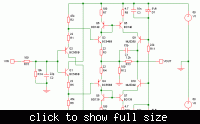
Maybe something like this? It's quite fast.....


The input impedance is 10K, so it will work fine with your signal generator.

The output impedance is about 100 Ohms. I don't know your requirements. What will the output of the amplifier be connected to?
 

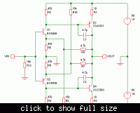
Here's a much simpler circuit that seems to work just as well.


I prefer this one. The other circuit was too complicated.
 
hi,
i want to apply this amplifier output to cell culture.
 

That sounds interesting. Do you know what the electrical resistance of the culture is, or how much current the amplifier must drive through it?

Do you only want to use sine waves up to 300KHz, or other waveforms too, e.g. square waves?
 

i don't know about electrical impedance of cell culture and i'm searching, but i want to pass 2-7 mA,
 

The circuit in post 5 is OK then. It can pass up to about +-50mA.

- - - Updated - - -

The circuit can be improved a bit though. Do you know something about electronics, so you can finish the design?
 

The circuit in post 5 is OK then. It can pass up to about +-50mA.

- - - Updated - - -

The circuit can be improved a bit though. Do you know something about electronics, so you can finish the design?

hi,
i used the circuit in post 5 and load is a cuvette with water, but voltage is dropped.
 

What do you mean by "voltage is dropped"?
What is output voltage with no load?
What is output voltage connected to load?

Do you know how much current is passed? Maybe the load is drawing more current than you expected.

How is the amplifier connected to the cuvette? Can you show a picture?
 

What do you mean by "voltage is dropped"?
What is output voltage with no load?
What is output voltage connected to load?

Do you know how much current is passed? Maybe the load is drawing more current than you expected.

How is the amplifier connected to the cuvette? Can you show a picture?

cuvette id connected to circuit's output directly, output voltage with no load is 18v and with load drop to 8v.
i want to stimulate MCF-7 in cuvette.
 

cuvette id connected to circuit's output directly
Cuvette is made of glass or plastic, isn't it? How do you connect the amplifier to that, or to the liquid inside? Are there metal plates inside on two sides or at the top and bottom, or do you stick two electrodes in at the top, or what?

output voltage with no load is 18v
Do you mean 18V RMS? That is only 50V pk-pk. I thought you want 100V pk-pk.

and with load drop to 8v.
The load must be drawing a high current. Did you measure it?

If you want higher voltage, why don't you increase the output from the signal generator?

- - - Updated - - -

What kind of power supply are you using? If the voltage is too low, the amplifier may not work properly.
 

Cuvette is made of glass or plastic, isn't it? How do you connect the amplifier to that, or to the liquid inside? Are there metal plates inside on two sides or at the top and bottom, or do you stick two electrodes in at the top, or what?


Do you mean 18V RMS? That is only 50V pk-pk. I thought you want 100V pk-pk.


The load must be drawing a high current. Did you measure it?

If you want higher voltage, why don't you increase the output from the signal generator?

- - - Updated - - -

What kind of power supply are you using? If the voltage is too low, the amplifier may not work properly.

cuvette is plastic with metal plates inside and outside on two sides and electrodes stick two sides,
power supply can support to 60v and i can use higher voltage from signal generator but i want to solve dropping voltage problem.
i don't know more about impedance of this load and want to match impedance to over problem.
i read something about MCF-7:it's impedance is decreased form 3000 t0 1450 ohm by 11-101 kHz
 

cuvette is plastic with metal plates inside and outside on two sides and electrodes stick two sides,
power supply can support to 60v and i can use higher voltage from signal generator but i want to solve dropping voltage problem.
i don't know more about impedance of this load and want to match impedance to over problem.

hi,
there is another problem,i used +-40v power supply and had good output but when used +-50v, R2,Q3 and Q4 are damaged. can you tell me why?
 

i used +-40v power supply and had good output but when used +-50v, R2,Q3 and Q4 are damaged.
Most likely: Q3 or Q4 got too hot. They should be mounted on heatsinks.

Also possible: Q1 failed first and caused the others to fail. Did you use the right transistors, or others with a high voltage rating?

The amp is designed to work best with a supply of +-60V. +-50V is OK, but +-40V is too low. It will still work with +-40V, but the output will be distorted. If you want to use lower power supply voltages, then the design should be changed a bit.

output voltage with no load is 18v and with load drop to 8v.
i want to solve dropping voltage problem.
That's not easy to fix. The amplifier has an output impedance of about 100 Ohms. If the output voltage drops to about half when the load is connected, that means the load is also about 100 Ohms.

If you don't want the voltage to drop, then the amplifier must have a much lower output impedance. That means you need a different circuit - this one can not be changed to have very low output impedance.

~~~~~~~~~~~~~~~~~~~~~~~~~~~~~~~~~~~~~~~

I have a concern here. You said that you want to pass a current of 2mA to 7mA, but now it seems you are passing a current 10 times higher than that.

I estimate 8V / 100 Ohms = 80mA. Is that what you want? If you put 100V pk-pk into that cuvette, you are likely to cook the cell culture, instead of stimulating the cancer. Perhaps it would be better to work at lower voltage?

Which is more important to you - the voltage applied or the current that is passed. Maybe it would be more useful to control the current instead of the voltage?

btw, did you try to measure the current that was passed through the load? This is quite easy - just connect a resistor (say 10 Ohms) in series with the load, and measure the voltage across the resistor.
 

plz help me, i need amplifier in f=<500khz,output impedance of signal generator=600 ohms, load impedance=100 ohms,and need output of 20-50vp-p.
 

how can i limit the current of output?
Most likely: Q3 or Q4 got too hot. They should be mounted on heatsinks.

Also possible: Q1 failed first and caused the others to fail. Did you use the right transistors, or others with a high voltage rating?

The amp is designed to work best with a supply of +-60V. +-50V is OK, but +-40V is too low. It will still work with +-40V, but the output will be distorted. If you want to use lower power supply voltages, then the design should be changed a bit.


That's not easy to fix. The amplifier has an output impedance of about 100 Ohms. If the output voltage drops to about half when the load is connected, that means the load is also about 100 Ohms.

If you don't want the voltage to drop, then the amplifier must have a much lower output impedance. That means you need a different circuit - this one can not be changed to have very low output impedance.

~~~~~~~~~~~~~~~~~~~~~~~~~~~~~~~~~~~~~~~

I have a concern here. You said that you want to pass a current of 2mA to 7mA, but now it seems you are passing a current 10 times higher than that.

I estimate 8V / 100 Ohms = 80mA. Is that what you want? If you put 100V pk-pk into that cuvette, you are likely to cook the cell culture, instead of stimulating the cancer. Perhaps it would be better to work at lower voltage?

Which is more important to you - the voltage applied or the current that is passed. Maybe it would be more useful to control the current instead of the voltage?

btw, did you try to measure the current that was passed through the load? This is quite easy - just connect a resistor (say 10 Ohms) in series with the load, and measure the voltage across the resistor.

how can i limit the current of output in topic 5?
 
Last edited:

hi again,
i could measure the capacitance of the load and now i think i need an amplifier with approximately 10 ohms output impedance, and no need to high current (i need =<5 mA).
i will be happy if help.
thank you
 
Last edited:

Status
Not open for further replies.

Similar threads

Part and Inventory Search

Welcome to EDABoard.com

Sponsor

Back
Top