Continue to Site

Welcome to EDAboard.com

Welcome to our site! EDAboard.com is an international Electronics Discussion Forum focused on EDA software, circuits, schematics, books, theory, papers, asic, pld, 8051, DSP, Network, RF, Analog Design, PCB, Service Manuals... and a whole lot more! To participate you need to register. Registration is free. Click here to register now.

+/-10v to 0-5v conversion

Status
Not open for further replies.

nbrand86

Newbie level 6
Newbie level 6
Joined
Apr 19, 2012
Messages
11
Helped
0
Reputation
0
Reaction score
0
Trophy points
1,281
Activity points
1,373
I am using a Galil motion controller which outputs motor control signal withing -10v to +10v range. But the amplifier I am using accepts the input within 0v to 5v.
I need to make a circuit in between witch takes input +/- 10 and outputs 0 to 5v proportionally.
The center value is gonna be shifted from 0(input) to 2.5V(output)

As far as I know, it could be done by op amps.
Please let me know any recommendation of a certain chip with op-amp or a schematic.
Thanks.
 

yes, need the output within the proportional range of 0v to 5v (2.5 center)
But the schematic you proposed looks like too complicated.
Is their any simpler way to shift this voltage range?
Thanks anyway.
 

You may use the Summing Amplifier, a circuit based upon the standard Inverting Operational Amplifier configuration that can be used for combining multiple inputs.

Vout = Vin * (R2+R1)R4/R1(R3+R4) - Vref * R2/R1

From the initial conditions we need to solve the equations for x=R2/R1, y = R3/R4.
There are many possibilities as we may choose for a suitable voltage reference.
See the two circuits using a Vref = 1.25V and Vref 2.5V in the attached pictures.
 

Attachments

  • AO sum.png
    AO sum.png
    26.6 KB · Views: 2,178
  • AO test circuit.png
    AO test circuit.png
    66 KB · Views: 843
  • AO test circuit 2.png
    AO test circuit 2.png
    72.5 KB · Views: 1,000
If you can use a voltage divider, here is one that would work: https://cq.cx/interface.pl#6 You just need to scale it for your range. Voltage dividers have the problem of being affected by load, though, so this only works well with an isolated load.
 

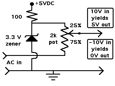
Here is my solution using a resistor divider.

The pot can be a different value.

The zener regulator is not absolutely necessary, if you already have a stable DC source (such as the 5V supply). You can substitute a pot (maybe 2k). Dial it down to 3.3V.

57_1334898628.gif
 
  • Like
Reactions: tpetar

    tpetar

    Points: 2
    Helpful Answer Positive Rating
Thanks for all the replies. Also I found this circuit with different ranges.
OpAmp-Level-Shifter.gif

I made the following changes according to my requirements ( input is +/- 10 and the out put is 0 to 5V, 2.5 center)
Please let me know whether I am right or wrong in the following data.
Vpp = 20v
Vref = 2.5v
A= .25
R1= 100k
R4= 25k

I assumed, R1=R3 and R2=R4 as that website mentioned.
so A = (R4/R1) x (R1+R2)/(R3+R4)
A = R4/R1

If the data is correct can you suggest me a chip I can use for the op amp?
Thanks a lot.
 

Status
Not open for further replies.

Similar threads

Part and Inventory Search

Welcome to EDABoard.com

Sponsor

Back
Top