Continue to Site

Welcome to EDAboard.com

Welcome to our site! EDAboard.com is an international Electronics Discussion Forum focused on EDA software, circuits, schematics, books, theory, papers, asic, pld, 8051, DSP, Network, RF, Analog Design, PCB, Service Manuals... and a whole lot more! To participate you need to register. Registration is free. Click here to register now.

PIR sensor triggering problem

Status
Not open for further replies.

decepticon

Newbie level 6
Newbie level 6
Joined
Dec 25, 2011
Messages
14
Helped
0
Reputation
0
Reaction score
0
Trophy points
1,281
Location
Solar System
Activity points
1,384
Hi,

I got a new PIR sensor (lhi 968) and tested it. The following are the connections that I made

GND pin : ground

D pin : +5V dc supply

S pin : CRO (to view the output)

But no matter how I tried to trigger the circuit (waving hands, blowing air, boogie dancing) the sensor gave a constant output of 0.8V. What's the problem?
 

That's a dual sensors PIR element.
So the PIR itself has two slots in it, each area sensor is made of a special material that is sensitive to IR. Both sensors are connected out of phase such that any excitation that is common to both the sensors cancel out. When the sensor is idle, both slots detect the same amount of IR, like the ambient amount radiated from the room or walls or outdoors, but no signal is generated on the output.
In order to obtain a valid signal output, a body with infrared emission around 10µm passing before the PIR element must excites first one sensors and then the other sensor. To improve the range and detection angle, Fresnel lens must be used.


Fresnel-Lens.jpg


‘’A Fresnel lens is a plano convex lens that has been collapsed on itself to form a flat lens that retains its
optical characteristics, but is thinner and has lesser absorption losses’’
When an object moves in front of the sensor, the dual elements are excited one after other and the resultant output is a +Ve signal followed by a –Ve signal. These change pulses are what is detected.

**broken link removed**


sensorpir.jpg


More details here:

https://www.ladyada.net/learn/sensors/pir.html
 
Hi,

I got a new PIR sensor (lhi 968) and tested it. The following are the connections that I made

GND pin : ground

D pin : +5V dc supply

S pin : CRO (to view the output)

But no matter how I tried to trigger the circuit (waving hands, blowing air, boogie dancing) the sensor gave a constant output of 0.8V. What's the problem?

check : How to interface PIR modules with PIC microcontrollers https://www.edaboard.com/blog/1436/
for code, circuit, picture of a PIR module, picture of a working model etc
 

Hi,

I got a new PIR sensor (lhi 968) and tested it. The following are the connections that I made

GND pin : ground

D pin : +5V dc supply

S pin : CRO (to view the output)

But no matter how I tried to trigger the circuit (waving hands, blowing air, boogie dancing) the sensor gave a constant output of 0.8V. What's the problem?
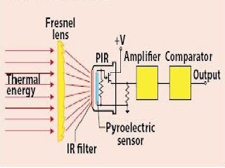
There are two important problems:
1. The PIR detector output must be loaded with a high impedance. If you used a voltmeter with 10 kOhm internal resistance, your reading is possibly correct, but:
2. the following amplifiers have a typical gain of 10 000 times, and the frequency range from 1 to 20 Hz. The "AC" voltage output from a PIR sensor is ~ 0.1 millivolt typically when you wave your hand before it. The Fresnel lens makes the moving warm object alternating the temperature input. Fixed objects only vary the output due to their temperature by several microvolts.

Find a working complete PIR detector (people often discard them when the relay fails) and test it for Alarm output. Typically you will find a 555 timer inside which generates a pulse output when triggered. You can test your sensor in it; Notice the gain and response of the signal amplifier, typically using LM324 or a similar opamp.
 

Status
Not open for further replies.

Part and Inventory Search

Welcome to EDABoard.com

Sponsor

Back
Top