Continue to Site

Welcome to EDAboard.com

Welcome to our site! EDAboard.com is an international Electronics Discussion Forum focused on EDA software, circuits, schematics, books, theory, papers, asic, pld, 8051, DSP, Network, RF, Analog Design, PCB, Service Manuals... and a whole lot more! To participate you need to register. Registration is free. Click here to register now.

Phase shifter circuit

Status
Not open for further replies.

Tom2

Full Member level 5
Full Member level 5
Joined
Nov 11, 2006
Messages
318
Helped
3
Reputation
6
Reaction score
3
Trophy points
1,298
Visit site
Activity points
3,457
I would like to design a phase shifter circuit which has the ability to shift the phase of the input voltage to 90,180 and 270 degree (different circuit each time). I would like to ask for a clue how to design this or (if there is any component available in the market for this purpose).
 

I speak about 150KHZ -200kHZ

---------- Post added at 02:20 ---------- Previous post was at 02:18 ----------

(the frequency is fixed)
 

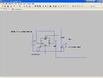
Install ltspice 4
New Bitmap Image.JPG
 

What is that? can you give explanations? I was thinking for something with capacitance,... .
 

What about the input waveform? Square? Sine?

At least for sinewaves, filtering is a way to phase shift. How much depends on the order of the low pass filter that is used: 90° for 1st order, 180 with a 2nd and so one... (multiples of 90)

The matter is that filtering means attenuation of signal so it have to come along with amplification. You may find interesting to look at active filters.

Hope this could help.

C U!
 
What about the input waveform? Square? Sine?
At least for sinewaves, filtering is a way to phase shift. How much depends on the order of the low pass filter that is used: 90° for 1st order, 180 with a 2nd and so one... (multiples of 90)
The matter is that filtering means attenuation of signal so it have to come along with amplification. You may find interesting to look at active filters.
Hope this could help.
C U!

The obvious and most simple solution is a chain of 3 integrators - each with a phase shift of 90 deg.
Depending on the signal frequency-to-time constant ratio you can have an overall gain or attenuation.
 
  • Like
Reactions: dselec

    dselec

    Points: 2
    Helpful Answer Positive Rating
What is that? can you give explanations? I was thinking for something with capacitance,... .
this is a very accurate phase shifter (u can get by converting your ac to pulse do the shift then convert it back to sine with filter )you need to install ltspice ill help u .
if u are looking for a pure analog shifter (not sure there is such a thing)its very complicated and expensive , the is a position
transformer that can give u any phase for a fix frequency . what is the freq. range ?
RESOLVER
resolver -

Because ther is 90 deg shift between voltage and current these circuit should work .Analog=http://www.massmind.org/images/www/hobby_elec/e_ckt20_2.htm
 
Last edited:

The obvious and most simple solution is a chain of 3 integrators - each with a phase shift of 90 deg.
Depending on the signal frequency-to-time constant ratio you can have an overall gain or attenuation.

Hi!

That's right! This way you don't have to worry about your filter cut off frequency. But for me an integrator is a particular case of active low pass filter.

There's a better solution, in case unity gain over whole frequency domain is required (personally i think it may be a key specification). I made some investigation and found that all pass filter is a good candidate.

**broken link removed**.

All-pass filter - Wikipedia, the free encyclopedia
 

There's a better solution, in case unity gain over whole frequency domain is required.
You can't in fact realize an analog circuit with constant gain and absolute phase shift over a frequency range. Wide band phase shifters can be only implemented as differential (relative) phase shifters, as shown in the link. Using this method, you can e.g. implement wideband SSB modulators, which is the usual motivation to do it for audio signals. The circuit achieves 90° differential phase only in an approximation, but the error can be very small.

But it's not clearly said, if constant phase and gain is required for the 150 to 200 kHz frequency range and which error can be tolerated.
 
HI,
can you please help to understand the operation how 1st order filtering work as a 90 degree phase shifting circuit?
Thnx in advance
 

Generally i when i charge a capacitor with ac current the voltage on the cap will be 90 shift from the current charging it.
 
Last edited:

Generally i when i charge a capacitor with ac current the voltage on the cap will be 90 shift from the current charging it.
Which refers to an integrator respectively a low pass with zero pole frequency. An inverting OP integrator would be another way to implement it. A first order passive circuit with voltage in/voltage out can't exactly achieve 90 degree and will approach it with large attenuation.
 
Generally i when i charge a capacitor with ac current the voltage on the cap will be 90 shift from the current charging it.


Yes u r right.......But I don't need to shifty the phase of voltage with respect to signal........I have to shift phase of output signal with respect to input signal......


if u can please help me.........I need it fast......

Thanks in advance
 

The All-pass Filter reference by arocklife in Post #9 is an interesting phase-shift circuit that can give a phase shift of 0° to 180° (adjustable by R) at a fixed frequency with a constant gain of 1. That output phase varies with frequency and/or the value of R but not the output signal amplitude (at least within the ratio tolerance of the two Rx's).
 
Last edited:

Status
Not open for further replies.

Similar threads

Part and Inventory Search

Welcome to EDABoard.com

Sponsor

Back
Top