Continue to Site

Welcome to EDAboard.com

Welcome to our site! EDAboard.com is an international Electronics Discussion Forum focused on EDA software, circuits, schematics, books, theory, papers, asic, pld, 8051, DSP, Network, RF, Analog Design, PCB, Service Manuals... and a whole lot more! To participate you need to register. Registration is free. Click here to register now.

Solar Tracker Schematic, need help to design mechanical part

Status
Not open for further replies.

jami007

Full Member level 3
Full Member level 3
Joined
Jan 19, 2010
Messages
179
Helped
43
Reputation
86
Reaction score
44
Trophy points
1,308
Location
Pakistan
Activity points
2,293
Here is a simple solar tracker, working fine, now I want to design mechanical part so need your help, I'm thinking to use Aluminum instead of iron and wood or steel.

below is the source link

**broken link removed**

here is a mechanical design, but I want to improve its design.
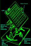
solar.png

I also need some idea to reset solar panel initial position after sunset
Best Regards
 

Attachments

  • Solar Tracker.zip
    28.4 KB · Views: 354
Last edited:

The design is good for higher latitudes. It will track the sun when it is low in the sky. Also when it rises and sets during cold season.

That looks like a counterweight at the back. Good idea. You can make that part out of steel of course.

Questions:

* Is the base supposed to be fastened to a roof? Does it allow access for you to clear away water, leaves, debris, wasp nests, etc.

* Is the center hold-down sturdy enough so the assembly will not tip over in high winds? For similar reasons is the assembly as short as possible?

* Are the wheels large enough that they can easily roll over leaf stems, twigs, etc.?

* Do you intend for the tracker to locate the sun automatically at sunrise (east horizon)?

* Do the curved rails permit sufficient travel of the assembly, so it can turn directly toward the east and west?

* Do the motors spin slowly enough to make tiny movements as the sun moves slowly across the sky?

* Can wiring be positioned to be clear of moving parts, yet without repeated sharp bending and causing wires to break?

* Will this design be able to follow the sun as it transitions through all 4 quadrants of the sky near zenith (as it can do if you are located within 23.5 degrees of the equator).

==================

The up-down-left-right motion is an economical way to obtain alt-azimuth movement.

However the sun can be tracked over the entire day with just one motor. The axis of turning is around the polar axis.

Such a design would require a completely revised rack to support the solar panel.

The other motor will only need to turn on briefly every few weeks as the seasons change. It will tilt the panel higher or lower in the sky as the sun tracks a higher or lower arc in the sky.

Or the second motor can be omitted entirely, and the panel can be tilted manually at the change of seasons, four times a year (maybe as little as twice a year).
 

did you asked to answer these question??? or they are just for purpose of understanding
 

The design can work as is, above a certain latitude. Of the questions I brought up, at least a few will need to be addressed in certain real-life situations.

I did not have a tracker for my solar panels. I put them on the roof which was sloped down toward the south. I figured that was adequate for the time being, until I needed optimum performance if the grid were to go down longterm.

My panels got leaves and twigs on them. Wasps built nests underneath one or two of them.
 

Hey everybody, can someone post a single sided board layout of this tracker in Proteus, I'm not good in pcb design, so it will take much longer for me to design a pcb, if someone can help it will definately appriciated by everyone.

Best regards
 

Here is a PCB design of this Solar tracker, pdf and proteus original files attached

Solar Tracker  PCB.jpg

Solar Tracker Top PCB.jpg

Solar Tracker bottom PCB.jpg
 

Attachments

  • PCB design.zip
    119.9 KB · Views: 296
  • Like
Reactions: paralk

    paralk

    Points: 2
    Helpful Answer Positive Rating
here are the pdf files for PCB
 

Attachments

  • solar tracker bottom.PDF
    394.8 KB · Views: 329
  • solar tracker Layout.PDF
    60.4 KB · Views: 303
  • solar tracker bottom mirrored.PDF
    396.6 KB · Views: 310
Last edited:
Status
Not open for further replies.

Part and Inventory Search

Welcome to EDABoard.com

Sponsor

Back
Top