Continue to Site

Welcome to EDAboard.com

Welcome to our site! EDAboard.com is an international Electronics Discussion Forum focused on EDA software, circuits, schematics, books, theory, papers, asic, pld, 8051, DSP, Network, RF, Analog Design, PCB, Service Manuals... and a whole lot more! To participate you need to register. Registration is free. Click here to register now.

How to obtain the proper S-parameter values for low pass filter Richard's method

Status
Not open for further replies.

btv_murthy

Full Member level 3
Full Member level 3
Joined
Nov 29, 2011
Messages
159
Helped
9
Reputation
18
Reaction score
9
Trophy points
1,298
Location
BANGALORE
Activity points
2,719
Dear Sir,

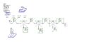
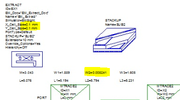
I tried for the Richard's transformation method lowpass filter design , got the proper s-parameter values for the schematic simulation. But I didn't get expected s-parameter values for the EM extraction. Design values are as follows.

Z0= 50 Ohm, f = 4 GHz, H=1.6mm , T =0.036, dielectric constant =4.4, Tangential loss =0.001

I am expecting following values for both SCHEMATIC and EM Extraction


Frequency DB S(1,1) DB S(2,1)

4GHz -3.1084 -3.0946
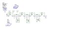
Herewith I am attaching the present getting layout and schematic diagram. Can u help anybody to get expected s-parameter values
 

Attachments

  • LPF_STEPPED RICHARD.jpg
    LPF_STEPPED RICHARD.jpg
    81.5 KB · Views: 159
  • layout_Richard LPF.jpg
    layout_Richard LPF.jpg
    52.1 KB · Views: 149

Check the cell size for your EM extraction. From what I can see, the cell size defined in the extraction block is much bigger than the width of the narrow lines.

54_1327428679.png
 

Some other hints: you can not make the high impedance transmission lines so narrow that they are very lossy and expect the performance to look like the lumped element prototype. ALso, the richards transform is a narrowband thing....you have to decide what frequency (i.e. what stub lengths) you want the transmission line model to best match the lumped model. For a lpf, I usually make the two match as closely as possible at the cuttoff frequency Fc of the lpf.
 

Check the cell size for your EM extraction. From what I can see, the cell size defined in the extraction block is much bigger than the width of the narrow lines.

54_1327428679.png
Volker Sir,

I changed the cell sizes to 0.01mm for both x & y cell size , am getting error. Even I changed the MWO simulator like ,OEA, ACE, VELOCE RF and AXIAM, for those simulator also getting the error sir.
 

Attachments

  • LPF_RICHARDSON.jpg
    LPF_RICHARDSON.jpg
    81.7 KB · Views: 103
  • 11-LPF-RICHARD'S METHOD.doc
    459.5 KB · Views: 80

I changed the cell sizes to 0.01mm for both x & y cell size , am getting error.

It is difficult to help if we don't know what error you get. Certainly, a small cell size will require additional memory. But if you have these ultra narrow lines, you need to set the cell size small enough to mesh the narrow lines.

But anyway - as biff44 wrote, the <10µm line width is a problem anyway. Redesign your filter with a wider line (maybe 50µm or more) that can realistically be manufactured.
VOLKER Sir,

It is showing the following errors sir,

1. Not enough memory to creat moment tables
2. An error occured in the remote em simulator "EM Sight " fatal error
3. EX1 unable to simulate the circuit refered by the model
4. unable to enumerate the circuit
5.An error occured in the simulator while processing EM EXTRACT_DOC.SFDOC
 

1. Not enough memory to creat moment tables

Ok, makes sense. This is because the mesh with small cell size is more complex -> needs more memory. But if you simulate with 0.1mm cell size, all lines will be simulated with n*0.1mm width. The narrow lines from your schematic will be EM-simulated with 1 cell = 100µm width. This is a big difference from the line width that you defined in the schematic.

If you can not use a smaller cell size in EM, then you should re-design for wider line width.
 

Status
Not open for further replies.

Part and Inventory Search

Welcome to EDABoard.com

Sponsor

Back
Top