Continue to Site

Welcome to EDAboard.com

Welcome to our site! EDAboard.com is an international Electronics Discussion Forum focused on EDA software, circuits, schematics, books, theory, papers, asic, pld, 8051, DSP, Network, RF, Analog Design, PCB, Service Manuals... and a whole lot more! To participate you need to register. Registration is free. Click here to register now.

Some doubts in amplifier.......

Status
Not open for further replies.

subbuindia

Member level 5
Member level 5
Joined
Dec 13, 2011
Messages
87
Helped
11
Reputation
22
Reaction score
10
Trophy points
1,288
Location
Vellalacheruvu(AP), India
Activity points
1,908
Hi friends.........

1. In CE amplifier, why the output and input are phase shifted by 180 degrees. You may say the voltage drop at collector resistor is increasing by increasing the collector current, then voltage drop at collector terminal will decrease. But, how the phase shift is related to it? And even, if voltage drop decreases (means output decreases) at collector terminal, then how can we say, it act as amplifier? Please, explain with any example? Hope, It is clear for you.


2. Input resistance is nothing but the ratio of input voltage to the input current. Then, why the input resistance of CC amplifier is very high compared to CE amplifier? (I'm saying these two amplifiers have the same input current and same input voltage. Is it correct?) Hope, it is clear for you.

Thanks to all......
 

1) CE is basically an inverter; as input voltage goes higher, output voltage goes lower. If you invert a sinewave, it's 180 degrees phase shifted by definition. A small CHANGE in input voltage may cause a large CHANGE in output voltage-that's amplification. A CE amplfier has negative gain, but it still amplifies.

2)The CC and CE amplifier do not have the 'same input current and input voltage'. The CC (emitter follower) is basically a current amplifier (or a voltage buffer) The output voltage is nearly equal to the input voltage, but the output current is much larger than the input current.
 

When we talk about the Phase shift of 180 deg in CE amp, it's flow of small signal collector current that flows opposite to the measurement of Output Voltage across load
i.e. Beta*Ib flows out of collector terminal, whose direction is opposite to the measurement of our Output voltage,
small signal input current "ib" is flowing in the same direction ,our "Vin" is measured.i.e across the Base-to-emitter assuming emitter is small signal ground.
Coming to your increasing Collector current and voltage drop:-
I think the changing current you r talking is abt the incremental current. Two currents are taken into account
1. Quescent Collector current ( which is dependent on the Biasing, Once CE circuit is biased to operate in Active region for Amplification
, the quescent values remain fixed)
2. Incremental or small signal current ( it changes according to the polarity of the incremental signal)

As the incremental collector current "ic" = ( negative of Beta*ib ) flowing into load (RC|| ro|| RL)
voltage drop is negative and Beta times the incremental input current "ib "
Amplification is must , if ur transistor is Once biased in Active region and a small signal is applied.
Input Resistance:-
Input Impedance in general or Resistance (without taking capacitance effects )= Incremental input voltage /Incremental input current @ RL = infinite .i.e Output is open
For CE ; if out put is open , Beta*ib =0 ; vin/iin=rPI( assuming no RE )
For CC; output terminal is changed to Emitter , so it will have some term with RL also

In a practical amplifier you don't change the Quescent currents , so the Quescent currents are fixed to operate in a desired region(Active region for Amplification)


Inversion and phase shift are entirely different.
[/URL]

This statement generates the following two questions:

1.) Does the above claim also apply to "phase inversion" (of a continuous sine wave) ?
(Usage of the term "inversion" is not sufficient; you must indicate which parameter is to be "inverted")

2.) How do you calculate the phase shift (+90 deg) of an (ideal) inverting Miller-integrator?
 

1.) Does the above claim also apply to "phase inversion" (of a continuous sine wave) ?

If you are referring to the common misconception of 180° difference between the emitter and collector waveforms in a common emitter amplifier, yes.

( Use of the term "inversion" is not sufficient; you must indicate which parameter is to be "inverted")

Very well, if you want to de pedantic, between the collector and emitter waveforms of a common emitter amplifier there is a sign inversioin.

How do you calculate the phase shift (+90 deg) of an (ideal) inverting Miller-integrator?

The question is irrelevant.

A phase change necessitates a signal being modified by reactive components in its path, as well you know - or should know.

There is nothing reactive in the path between the emitter and collector of a common emitter stage.

An in integrator is reactive, as well you know.
 

If you are referring to the common misconception of 180° difference between the emitter and collector waveforms in a common emitter amplifier, yes.

I suppose, you mean "...between base and collector" ?
Beside this, I would ask for your explanation of the common term "phase inversion". What does it mean and how can it be achieved in practice? Only by reactive elements (delay effects) ?

Very well, if you want to de pedantic, between the collector and emitter waveforms of a common emitter amplifier there is a sign inversioin.
I am not quite sure if the attempt to clarify definitions should be called "pedantry". In contrary, I believe that - in particular for beginners - a clear definition of terms (especially if they are similar) is of great importance. Don't you think so? A good example for the necessity to clarify things is your contribution #4, in which you oppose some earlier statements regarding phase shift.
That is the only reason I jumped (again) into this discussion, which we have started some weeks ago in another thread of this forum.
I remember well your way to explain the term "phase shift" based on time delay effects (your diagram showing marked points on the sine wave).
In this context I kindly ask you to answer the following question:

Is it correct to say that a simple C-R high pass (for sinusoidal signals in the steady state mode) generates a positive phase shift between input and output?
If yes - will your explanation, which is based on the delay effect (see the principle of marked points), lead to the result that the high-pass is a non-causal system?

The question is irrelevant.
A phase change necessitates a signal being modified by reactive components in its path, as well you know - or should know.
There is nothing reactive in the path between the emitter and collector of a common emitter stage.
An in integrator is reactive, as well you know.

I am sorry, but I cannot see why the question (explanation of the phase shift of an inverting MILLER integrator) is "irrelevant".
Even if you consider it as "irrelevant", I kindly ask you to answer this question.

With kind regards
LvW
 
  • Like
Reactions: FvM

    FvM

    Points: 2
    Helpful Answer Positive Rating
I suppose, you mean "...between base and collector" ?

Yes, your supposition is correct.

Beside this, I would ask for your explanation of the common term "phase inversion".

It means, whenever I have seen the term, a sign inversion.

The rest of your contribution seems to be argument for the purpose of scoring points, argument for argument's sake, and is getting rather tiresome. If you want to do that, join a debating society. I won't indulge you.
 

Syncopator, if I showed you an oscilloscope trace showing two sinewaves where the peak of one occurred at the same time as the trough of the other, couldn't you say that one was 180 degrees out of phase of the other? The concept of phase is a mathematical one and has NOTHING to do with reactance. And I think poor Subuuindia's question was 'why is the output phase shifted (or inverted, if you must) from the input'. The point here is to help others understand, not rail on about nomenclature.
 

Syncopator, if I showed you an oscilloscope trace showing two sinewaves where the peak of one occurred at the same time as the trough of the other, couldn't you say that one was 180 degrees out of phase of the other?

No, I couldn't, and wouldn't. Because it's not true.


... why is the output phase shifted (or inverted, if you must) ...

Yes, I must.

The point here is to help others understand ...

I agree. And that applies equally well to those who give misleading answers.

... rail on about nomenclature.

If that's what it takes ....
 

The rest of your contribution seems to be argument for the purpose of scoring points, argument for argument's sake, and is getting rather tiresome. If you want to do that, join a debating society. I won't indulge you.

Thank you very much. You are right - I urgently need points.
Nevertheless, it is a pitty that you are not willing to answer two simple technical questions. I think, everybody in the forum who has followed this "discussion" knows the reason.
LvW

---------- Post added at 21:21 ---------- Previous post was at 20:17 ----------

Syncopator, if I showed you an oscilloscope trace showing two sinewaves where the peak of one occurred at the same time as the trough of the other, couldn't you say that one was 180 degrees out of phase of the other? The concept of phase is a mathematical one and has NOTHING to do with reactance. And I think poor Subuuindia's question was 'why is the output phase shifted (or inverted, if you must) from the input'. The point here is to help others understand, not rail on about nomenclature.

Hi Barry,

I suppose you will be not surprised if I agree with you - as far as the first part of your contribution is concerned.
However, I disagree with your last sentence regarding nomenclature.
As I have mentioned earlier, according to my experience it is very important for students and beginners to know the terms and to be familiar with the correct nomenclature.
For my opinion, this forms the basis for a correct understanding of tecnical and physical phenomena.
Here is an example for a technical term that very often is used with different (resp. false) meanings: open-loop gain, loop gain, gain of the open loop, gain with open loop.
(As you know, only some of these expressions are identical). I am not sure if everybody in this forum knows the difference.
Regards
LvW
 
  • Like
Reactions: FvM

    FvM

    Points: 2
    Helpful Answer Positive Rating
As to Q 1:

I'm in the camp who prefer to say 'inverted' or 'sign change' rather than '180 deg. phase difference'.

It's too easy to confuse 'phase difference' with 'phase shift' which is a different phenomenon in electronics, and which can be in any amount as well as 180.

As to Q 2:

The CC amp puts a load in the emitter leg. This has the effect of resisting bias flow. At the same time a voltage is created across the load by the current going through it.

To overcome the two effects combined, it is necessary to apply a greater bias voltage.

The bias voltage must be raised even more if the load has a diode junction.
 

Hi,

Definitions are important because without them we can not clearly communicate concepts.
We can take different definitions to a term like those being discussed in this thread. But we have to consider which definitions are usual and which are useful and meaningful.

It is usual, useful and meaningful to tell about amplitude and phase of transfer functions, impedances, spectra, etc.
Usually amplitude is defined as a real and positive magnitude. We could define it in such a way that it is allowed to be negative, but in that case the expression would not be unique: a sinusoid with amplutude A and phase phi could be described with amplitude -A and phase phi+pi.

It is usual, useful and meaningful to represent sinusoidal signals as phasors. With phasors, amplitude (positive) and phase have direct interpretations (modulus and argument). There is no need of nothing more. Inversion (or opposition) of a phasor is equivalent to a phase change of 180º. Otherwise, we should take a negative amplitude.


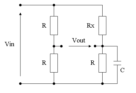
Please let mi give another example: the well known bridge of the figure.

53_1326433448.png


Vin is a sinusoidal voltage of some frequency.
Rx is a resistor that we will vary from 0 to Infinity.
Let's take the phasor of Vin as reference, and consider the phasor representing Vout.

When Rx=0, Vout is in phase with Vin (Vout=Vin/2).
Increasing Rx, the phase lag of Vout with respect to Vin increases. For some value of Rx, Vout is at -90 degrees of Vin with some amplitude (that depends of f*R*C).
Increasing Rx even more the phase lag increases, and for R->Inf we have phase->-180deg (Vout=-Vin/2).
In the condition R=Inf, we reach the condition at which Vout is at 180 deg of Vin. The phase changes gradually from 0 to -180 deg while Rx changes from 0 to Inf.
I'm willing to say that for R=Inf Vout is inverted with respect to Vin. But I don't agree that it is incorrect to say that they are 180º out of phase. For example, for a certain value of C, Rx=1000 (i.e. Gx=1/Rx=0.001) gives a phase difference of (say) 179.999°, so (at least in sake of continuity) we could'n disclaim that Gx=0 gives 180°.

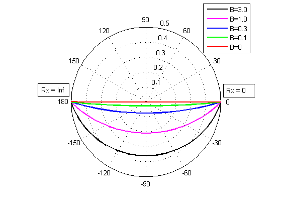
But let's go a little further. The following figure shows the extremes of the phasors for Rx changing from 0 to Inf. There are different lines for different values of the susceptance B of the capacitor (normalized to R).

37_1326435045.png


The cases B=3, B=1, B=0.3 and B=0.1 show what was described above.
If we remove the C (i.e. make B=0) we have a resistive Wheatstone bridge. No reactive components at all. In this case the transition between 0 and 180 deg is abrupt, but it is still a 180 deg phase change.
If you do agree that phase difference changes from 0 to 180º for any value of B (like 1, 0.1, ..., 1e-80, ..., as normalized values) surely you will accept that the same thing happens when B=0.

All your comments are welcome.
Regards

Z
 
  • Like
Reactions: LvW and FvM

    FvM

    Points: 2
    Helpful Answer Positive Rating

    LvW

    Points: 2
    Helpful Answer Positive Rating
If I understand right, you want to clarify, that from a phasors viewpoint, signal inversion is just a special case but not opposite to phase shift. I completely agree. The close relation of phase shift and signal inversion in electronic circuits has been previously discussed referring to oscillators based on an identity of 180 degree phase shift (by reactive elements) and signal inversion.

If it's reasonable to take the phasors viewpoint depends however on the problem and the purpose of analysis. I agree with Syncopator, that a simple signal inversion can be described more clearly as such. But I don't share the zeal in fighting erroneous believes, and to a lesser extent the demeanour.
 
  • Like
Reactions: LvW

    LvW

    Points: 2
    Helpful Answer Positive Rating
...... I agree with Syncopator, that a simple signal inversion can be described more clearly as such. .........

...."signal inversion"? What does it mean?

I know that this term is used very often. However, which parameter is multipled by "-1" - based on the physical phenomena that take place in common emitter amplifier stages?
A sinusoidal voltage is described by its frequency and amplitude - and, of course, the amplitude is inverted. Therefore, as the result of this amplitude inversion, there is a phase difference between input and output of 180 deg. That's all. The "phase" is a parameter that can be defined only in relation to a reference (not from the beginning).
Thus, for my opinion, it is not a "misconception" (as assumed by Syncopator) to speak about 180° difference between the emitter and collector waveforms.
It is the only correct way to describe the relation between both waveforms.
Of course, this applies to sinusoidal signals only. For other signals (non-sinusoidal, periodic, non-periodic) we should use the term "inversion".

Beyond that, I completely agree with Zorro's conspicious explanations.
 
  • Like
Reactions: FvM

    FvM

    Points: 2
    Helpful Answer Positive Rating
However, which parameter is multipled by "-1" - based on the physical phenomena that take place in common emitter amplifier stages?
The instantaneous amplitude, I thought so far. But I agree, it's not obvious that we are dealing with a time domain signal description at all. It depends on the context, there can be e.g. an "inversion" in frequency domain.

Thus, for my opinion, it is not a "misconception" (as assumed by Syncopator) to speak about 180° difference between the emitter and collector waveforms.
Surely not a misconception. Nevertheless the term inversion should be used where it obviously applies. I guess, you'll continue speaking about OPs in inverting amplifier configuration rather than phase shifting amplifiers.
 
  • Like
Reactions: LvW

    LvW

    Points: 2
    Helpful Answer Positive Rating
...
I guess, you'll continue speaking about OPs in inverting amplifier configuration rather than phase shifting amplifiers....

Yes, of course. In particular, because the phase difference between output and input is - as mentioned already - the result of the inversion of the instantaneous amplitude.
 

Syncopator, This is a huge claim ( a failed design due to misconceptions between phase difference of 180deg and inversion) and if this is true, please bring it on with details. Im sure everyone would agree with magnanimity and be willing to be proven wrong for gaining some knowledge. After all this is what we are here for. As per your claim, most books have got it wrong as well right. So please point us to one text that clears it.
 

Syncopator, This is a huge claim ( a failed design due to misconceptions between phase difference of 180deg and inversion)

Not my claim. It was something I read, decades ago, probably in Wireless World, in a short discourse on the subject. It stuck in my mind.
 

Status
Not open for further replies.

Similar threads

Part and Inventory Search

Welcome to EDABoard.com

Sponsor

Back
Top