Continue to Site

Welcome to EDAboard.com

Welcome to our site! EDAboard.com is an international Electronics Discussion Forum focused on EDA software, circuits, schematics, books, theory, papers, asic, pld, 8051, DSP, Network, RF, Analog Design, PCB, Service Manuals... and a whole lot more! To participate you need to register. Registration is free. Click here to register now.

Sinewave (~1.5 Mhz range) switching.

Status
Not open for further replies.

Simio

Newbie level 4
Newbie level 4
Joined
Jan 6, 2012
Messages
7
Helped
1
Reputation
2
Reaction score
1
Trophy points
1,283
Activity points
1,352
Hello.
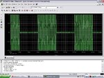
I need to design a circuit that will allow me to get a signal that is a sinewave (1.5 Mhz) which is "on" and "off" during certain periodic sets of time. (please see attached image).
Signal.png
I have already built a circuit for generating the sinewave and I also have a circuit that generates a pulse signal to control the "on" time of the sinewave.
My problem is that i don't know how to make these two signals interact in order to form the kind of signal I'm looking for.
What is the intelligent way to achieve this kind of signal (like the one in the attachment)? It is very important to maintain 0V during the sinewave's "off" time.
Thanks in advance!
 

Dear Simio
Hi
Welcome to EDA board .
do you know that how we create the PAM signal ? if yes , your answer is very simple . you can design a simple 1.5 MHZ fixed frequency oscillator and then you can design the square wave oscillator that its on time is about the off time of your sine wave , and you can do it with a simple PAM modulator.
Best Wishes
Goldsmith
 

Thanks Goldsmith.
I'm not familiar with PAM (I'm a ME student, haha) , but I can look into it. It is a digital implementation, right?
 

One way would be to make a simple class-A transistor amplifier circuit. You would feed your 1.5 MHz CW (continuous wave... "always on") signal into the base of the transistor amp. The supply voltage (on the drain/collector) would be supplied by your pulse-generator. When the pulse generator goes high, your amplifier has power, and lets the 1.5 Mhz signal through. When the pulse gen goes low, the amplifier has no power, and the 1.5 MHz signal doesn't pass through.

This assumes you can get something on the order of a few volts out of the pulse generator, and that it can source a decent bit of current (a few tens of mA's). This is form drain modulation (if you use a FET, since they have drains).

Another way to accomplish this task might be to use a transistor as a shorting switch. In that case, the 1.5 MHz source goes through a small series resistor (you'll see why later), to the output of your system. Connect a transistor from the output node to ground (1.5 MHz signal is on the drain/collector, source/emitter is grounded). The base/gate of the transistor would be driven by your pulse generator. When the pulse-gen output is low (0V), the shorting transistor is "off" and the 1.5 MHz signal passes right down the wire to the output. When the pulse-gen output goes high, the shorting transistor is turned "on", and the output wire is pulled to ground (0V). The 1.5 MHz oscillator will then "see" the series resistor as it's load (the other side of the resistor is connected to ground by the shorting "switch"). By giving the oscillator SOME load, you'll have a chance of keeping it stable while you toggle between opening and shorting the output node (oscillators don't typically like zero ohm loads, i.e short circuit).
 

Dear keith
Hi
What do you mean by analog switch?
Bes Wishes
Goldsmith
 

Dear Keith
Thanks for your reply. what are their perform frequency? and can they conduct at both half cycle ( my mean is at both negative and positive half cycle)?
Appreciate
Goldsmith
 

You can get very fast ones - up to GHz. They can only conduct within the supply rails so if you want to use them below ground you need a negative supply.

Keith
 
Even humble 4066 CMOS switches are good to several MHz. I've use 74HC4351 CMOS switches at 60MHz without any problems.
Provided you ensure the signal voltage falls within the switch supply rails it will keep it's zero point.

Brian.
 
Nice. I will try everything explained here.

In respect to the CMOS switch, I have some 4066 at disposal.
Since the signal (sinewave) goes, for example, from -5V to 5V : should the voltage supplied to the 4066 be at least -5V and 5V ?? And what about the control signal? Can it just be a 0-5V analogue pulse signal??

Thanks
 

Correct, the input must not exceed the supply rail so ensure both + and - rails are at least 5V and preferably a little higher but be careful not to exceed the manufacturers limit.
Unfortunately, the 4066 control voltage is referenced to the VSS pin so you would have to make it equal to the negative rail to turn the switch off and equal to the positive rail to turn it on. That's why I use 74HC4351s, they have logic level control even when handling negative voltages but they are multiplexers so to use them as a single pole switch you would have to out the control signal on one of the address lines. Vishay also make a range of analog switches with TTL level control.

Brian.
 
Ok.
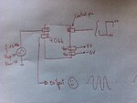
So something like this would work then? :
photo (8).JPG

If the answer is yes, the I have the two following rookie questions:

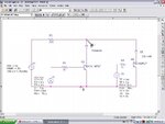
a) How to design a -5V..5V pulse generator? I was using the following design (which allows me to control the on and off time with potentiometers):

Is using this design from 0V to 10V and then offset it with -5V a good idea?? How does one achieve a simple -5V offset on a signal? (sorry for my noobness)

b) Let's consider both above issues resolved. I still need to amplify the resulting signal (switched sinewave) to 21 V peak to peak. What is the good way to do this??

THANKS!!
 

Dear simio
Again hi
for simultaneous voltage , you can not use 555 IC . and 555 can not give you 1.5MHZ frequency. you can use a simple relaxation oscillator with op amp , or you can use a sine wave oscillator such as wien bridge , and then you can limit it's amplitude , with zener diodes , or with a simple amplifier with bad Q point to achieve a simple square wave.
Best Wishes
Goldsmith
 

Why not simply use one of the many analog switches that can run from plus/minus supplies while still accepting a logic level control signal relative to 0V? Many of the newer devices don't even need a logic supply and will work with 5V, 3.3V and 2.5V logic.

Keith
 

Goldsmith: I use the 555 for the pulse control (~1kHz frequency). The sinewave comes from another device. Sorry for the poor explanation.

Keith: Yeah, that would be the best choice. Do you know some IC numbers of those switches. I have very limited selection for buying ICs, and given my timeframe, importing is not an option. I managed to get some 4066s but maybe (crossing fingers) I can find one of those.
 

The DG419 is the obvious one. It is quite an old device with quite a few manufacturers so you may be able to find it, or an equivalent.

Keith
 

Status
Not open for further replies.

Similar threads

Part and Inventory Search

Welcome to EDABoard.com

Sponsor

Back
Top