Continue to Site

Welcome to EDAboard.com

Welcome to our site! EDAboard.com is an international Electronics Discussion Forum focused on EDA software, circuits, schematics, books, theory, papers, asic, pld, 8051, DSP, Network, RF, Analog Design, PCB, Service Manuals... and a whole lot more! To participate you need to register. Registration is free. Click here to register now.

[SOLVED] Datasheet of DAP8E IC (SOP-8 package model)

Status
Not open for further replies.

Genovator

Advanced Member level 2
Joined
Dec 19, 2011
Messages
550
Helped
87
Reputation
174
Reaction score
84
Trophy points
1,328
Location
India
Activity points
4,632
Hi....
Could anyone help me by providing the datasheet of DAP8E ic which is a SOP-8 package model.
I have searched in google but haven't found any....
One hint: ON semiconductors manufactures it, but they have no details in their website.....
 

Re: need a datasheet....

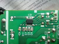
Is that the marking on the IC? If so, what is its function? What device is the chip in? Photos can sometimes help.

Keith.
 

Re: need a datasheet....

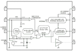
Dap08a ~ ncp1203
 

Attachments

  • 07011414366617.gif
    07011414366617.gif
    18.5 KB · Views: 483
  • ncp1200_157.jpg
    ncp1200_157.jpg
    48.3 KB · Views: 652
Re: need a datasheet....

Yes, DAP8E is the marking.... I found it in a 24v 1.2A power adapter of a canon printer.... I m not sure what it works, that is why I want its datasheet..... But I can assume that this ic can be used for safety of the circuit...

---------- Post added at 12:22 ---------- Previous post was at 12:20 ----------

to keith1200rs
Yes, DAP8E is the marking.... I found it in a 24v 1.2A power adapter of a canon printer.... I m not sure what it works, that is why I want its datasheet..... But I can assume that this ic can be used for safety of the circuit...

---------- Post added at 12:23 ---------- Previous post was at 12:22 ----------

to keith1200rs
Yes, DAP8E is the marking.... I found it in a 24v 1.2A power adapter of a canon printer.... I m not sure what it works, that is why I want its datasheet..... But I can assume that this ic can be used for safety of the circuit...

---------- Post added at 12:39 ---------- Previous post was at 12:23 ----------

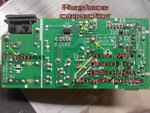
I cant take very close pic, but the following might help u......
 

Re: need a datasheet....

In which case mr_rf is on the right path although that isn't the exact chip as the marking wouldn't be DAP8E. You need to look through some data sheets looking at the chip markings to find it - they aren't the same as the chip number as they don't have room for a full number.

Keith
 

Re: need a datasheet....

although that isn't the exact chip as the marking wouldn't be DAP8E.
If I understand right, nobody knows, if and in which regard both are different, there are just guesses They may be functionally identical. In any case, the datasheet is completely answering Genovator's question "how it works".
 

Re: need a datasheet....

@Genovator

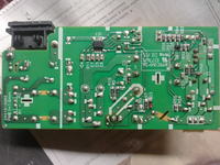
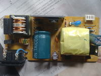
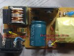
I don't see any physical damage, there is a blown fuse? If the transistor tested okay then i guess you have to replace the capacitor.
 

Attachments

  • 23_1324624122.jpg
    23_1324624122.jpg
    200.2 KB · Views: 332
  • 30_1324624123.jpg
    30_1324624123.jpg
    112.5 KB · Views: 329
Re: need a datasheet....

To, mister_rf
Yes, I know the fuse is blown. But when it was in good condition, the voltage output of this circuit was only 6.5V.
I have checked the circuit thoroughly, but there was no physical damage seen. I would blame the ic and the transistor.
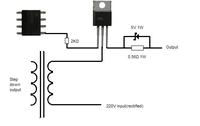
The 5th pin of that ic is connected with the gate of a Silicon N Channel MOS Switching Regulator(K3567).
The connection is something like this....

I can't understand which part to replace.....
And.... why that electrolytic capacitor have to be replaced???? It seems good physically...
 

Re: need a datasheet....

Try to test using a multimeter:
D6-D9 diodes in the bridge rectifier,
power MOSFET.
Resistor R10.

If MOSFET shorted, possible R10 blown up and IC1 destroyed.
Later check all the components marked in red.
Change the capacitor C11 (low capacity).
 

Attachments

  • DAP08E.JPG
    DAP08E.JPG
    54.6 KB · Views: 686
  • Components to test.JPG
    Components to test.JPG
    60.7 KB · Views: 555
I'm sorry to up this thread but I got the same problem..is this thread solved already? what part/s you replaced?
 

Hi 'kasamiko'...
Sorry I was off from edaboard for about 5 months....
My this project is till unfinished as i got no time for it... I started working now.
The IC DAP8E is a short circuit protection ic and it controlls the power MOSFET K3567 to 'run or break' the circuit.
In case of short-circuit, over voltage, etc. the ic stops the voltage output from pin 5 which controls the gate of MOSFET. The circuit breaks and thus output stops and the machine it is running is safe....
https://obrazki.elektroda.pl/95_1324639052.jpg
I am now planning to remove this security system and make the adapter simple....
I will post again when I am done...
 

Hi,

We have a similar power supply..as you noticed the output has a 3 pins connector for GND, B+ and another one I suspect as SENSE, REMOTE or FEEDBACK. I think this pin controls the power on/off of the main supply?


BR
 

I tried an experiment by just removing the transistor and make it 'short'. See this thread.

I blown out the fuse. I have not considered the PWM concept. The transistor is triggered and controlled by PWM. DAP8E is a PWM ic.

- - - Updated - - -

I tried an experiment by just removing the transistor and make it 'short'. See this thread.

I blown out the fuse. I have not considered the PWM concept. The transistor is triggered and controlled by PWM. DAP8E is a PWM ic.
 

The DAP8E is a PWM IC used in the smps and cannot be bypassed. NCP1203P60 is an direct equivalent which works in LCD monitor power supply.
 

Status
Not open for further replies.

Part and Inventory Search

Welcome to EDABoard.com

Sponsor

Back
Top