Continue to Site

Welcome to EDAboard.com

Welcome to our site! EDAboard.com is an international Electronics Discussion Forum focused on EDA software, circuits, schematics, books, theory, papers, asic, pld, 8051, DSP, Network, RF, Analog Design, PCB, Service Manuals... and a whole lot more! To participate you need to register. Registration is free. Click here to register now.

[SOLVED] What is the response of the given circuit

Status
Not open for further replies.

iVenky

Advanced Member level 2
Joined
Jul 11, 2011
Messages
584
Helped
37
Reputation
76
Reaction score
35
Trophy points
1,318
Location
College Station, Texas
Activity points
6,124
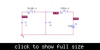
There are two capacitors C1 (4 F) and C2 (16 F). They are separated by a switch. The switch closes at t=0.
When t<0 the voltage in C1 is 10V. What will happen when the switch is closed? What will be the voltage across C1 and C2 now (ie t>0) ?

Thanks in advance.
 

There are two capacitors C1 (4 F) and C2 (16 F). They are separated by a switch. The switch closes at t=0.
When t<0 the voltage in C1 is 10V. What will happen when the switch is closed?

160 J of energy will be dissipated into heat and/or electromagnetic (radio) energy.
 

Unfortunately, your schematic is different from your previous description.

The original question (shorting a switch beteen two capacitors) involves infinite currents and an insolvable differential equation when assuming ideal components. Doesn't sound like a well considered text book exercise or homework problem.
 

There's an irresistible logic to thinking in terms of 10V on a 4F cap as being a certain number of units of energy.

Then this energy is divided among 20F.

Intuitively it seems as though the answer should be 2V.

My simulator confirms this is the case.
 

If you consider two capacitors C1 and C2 in parallel, separated by a switch, where C1 is charged at Vi volts, and C2 is not charged then:

Charge in C1: q1 = C1*Vi Coulombs
Charge in C1: q2 = 0 Coulombs

When the switch is closed the totale charge (q1+q2) must be conserved because there is no way to make it flows outside the circuit since it is insulated, then (if Vo is the final voltage across the two capacitors):

C1*vi + 0 = C1*Vo + C2*Vo

then:

Vo = C1/(C1+C2)*Vi

If C1=4F, C2=16F and Vi=10V:

Vo = 4/(16+4)*10 = 2V

You can note that the initial energy of the system was:

Ei = 0.5*C1*Vi^2 = 0.5*4*100 = 200 joule

but the final energy is only:

Ef = 0.5*C1*Vo^2 + 0.5*C2*Vo^2 = 0.5*4*4 + 0.5*16*4 = 40 joule

To balance the 200 - 40 = 160 joule, a spike (dirac pulse) will be generated when the switch is closed.
 
  • Like
Reactions: iVenky

    iVenky

    Points: 2
    Helpful Answer Positive Rating
Unfortunately, your schematic is different from your previous description.

The original question (shorting a switch beteen two capacitors) involves infinite currents and an insolvable differential equation when assuming ideal components. Doesn't sound like a well considered text book exercise or homework problem.
You can actually do this problem... assume a finite switch resistance and solve the problem. You'll find that the answer does not depend on resistance. You can also do it using charge conservation: Total charge before = total charge after (like I see albbg did).
 
Last edited:

If you consider two capacitors C1 and C2 in parallel, separated by a switch, where C1 is charged at Vi volts, and C2 is not charged then:

Charge in C1: q1 = C1*Vi Coulombs
Charge in C1: q2 = 0 Coulombs

When the switch is closed the totale charge (q1+q2) must be conserved because there is no way to make it flows outside the circuit since it is insulated, then (if Vo is the final voltage across the two capacitors):

C1*vi + 0 = C1*Vo + C2*Vo

then:

Vo = C1/(C1+C2)*Vi

If C1=4F, C2=16F and Vi=10V:

Vo = 4/(16+4)*10 = 2V

You can note that the initial energy of the system was:

Ei = 0.5*C1*Vi^2 = 0.5*4*100 = 200 joule

but the final energy is only:

Ef = 0.5*C1*Vo^2 + 0.5*C2*Vo^2 = 0.5*4*4 + 0.5*16*4 = 40 joule

To balance the 200 - 40 = 160 joule, a spike (dirac pulse) will be generated when the switch is closed.


Hello I understood about the charge conservation. But I couldn't understand that spike. What's that spike? (I know little about this switch thing.)

---------- Post added at 19:07 ---------- Previous post was at 19:04 ----------

How to do this in Pspice. I had attached the image in one of my previous posts and I think that there's something wrong in the schematic. I would be much obliged if you could say where the mistake is?
 

How to do this in Pspice. I had attached the image in one of my previous posts and I think that there's something wrong in the schematic. I would be much obliged if you could say where the mistake is?
SPICE doesn't know negative times or +0 and -0. It recognizes both switches closed during initial solution, resulting in balanced charges. You should close the switch at a time t1>0, not t=0.
But I couldn't understand that spike. What's that spike?
To turn the circuit in a real world one with finite currents, the switch must have a series resistance. The PSpice switch component already has, otherwise it would generate a simulation error.
 

SPICE doesn't know negative times or +0 and -0. It recognizes both switches closed during initial solution, resulting in balanced charges. You should close the switch at a time t1>0, not t=0.

How to change the time? Please help me.

Thanks in advance.
 

I know transient analysis. I don't know how to do that in pspice. I will try what you have said.

edaboard1.png

I tried what you have said but I didn't get it.

I would be much obliged if you help me.

Thankzzzzzzzz
 

O.K., I have forgotten something. The PSpice switch has a leakage resistance, you can see it in the device parameters. You need a shorting switch across the first capacitor or a similar means, e.g an initial condition statement to keep the capacitor discharged.
 

You'll need to connect the shorting switch in parallel to C1.
 

Status
Not open for further replies.

Part and Inventory Search

Welcome to EDABoard.com

Sponsor

Back
Top