Continue to Site

Welcome to EDAboard.com

Welcome to our site! EDAboard.com is an international Electronics Discussion Forum focused on EDA software, circuits, schematics, books, theory, papers, asic, pld, 8051, DSP, Network, RF, Analog Design, PCB, Service Manuals... and a whole lot more! To participate you need to register. Registration is free. Click here to register now.

about Laptop Adoptors?

Status
Not open for further replies.

Qaisar Azeemi

Full Member level 5
Full Member level 5
Joined
Feb 11, 2011
Messages
315
Helped
16
Reputation
32
Reaction score
15
Trophy points
1,298
Location
Peshawar, Pakistan, Pakistan
Activity points
3,829
about Laptop Adoptors Technology?

HI;

I note in some laptop adopters that they charge the specific Laptops even specific for specific versions of the same company brands. for example; the Laptop adopter for one dell Laptop(DL1) will not charge the other Dell laptop(DL2); it only power other laptop DL2 but not charge its battery.
i want to know the resion behind it;
1)what is the Technology used to make laptops compatible with a specific version? is it by sending some specific code or address to identify & charge the battery of the laptop?

2)if i made my own charger to charge the battery of Laptop... will it charge it or not?

3) if my confusion about compatibility is true; Can my Lead acid battery Charger charge the Battery of Laptop?

Hope to get Technology around replays.

Regards
 
Last edited:

I believe the laptop (its charging monitor circuit) examines the incoming voltage to see if it has spare power to charge the batteries, while running the computer too.

It must also check incoming voltage when you press the 'power' button.

However if the computer doesn't power up it may be due to other things than the supply being inadequate.

So if the computer doesn't start up you can't necessarily be sure whether the supply is too high or too low.

It's also conceivable that a computer is detects overmuch amounts of ripple, or noise, etc., on the incoming supply. And that some computers are more tolerant than others.

I have only seen two wires in the power plug to laptops. I've never heard of a certification code being transmitted. However I wouldn't put it past the manufacturers to do that, since they would love to squelch competition.
 

I have only seen two wires in the power plug to laptops. I've never heard of a certification code being transmitted. However I wouldn't put it past the manufacturers to do that, since they would love to squelch competition.
Most dell laptop adapters i have seen are with three wire connectivity. A center thin wire surrounded by +Ve wire and outer shielded ground wire. It leads to a 3 pin IC ( shape like a TO92 transistor).It identifies model of adapter through 12C protocol to laptop. If you can put this from some old charger then only it will charge battery otherwise only will power the laptop. Voltage is same, around 19.5V.
 
If the Two wired adopter and has the same specification in current and voltage the it will charge the battery. But if there is any adapter with special feed back from inside the Laptop to control the output of the adopter then it will be difficult. Obviously the connectors should be of same style.
 

it means there must be some Feed back ore recognization code interchange between Laptop adopter and battery inside the Laptop to avoid any kind of damage?
is there any mean to charge the battery of a Laptop with our own developed battery charger?
 

This is caused by Dell trying to stop people from using third party chargers. If the charger found not working properly, the problem lies not in the laptop nor the power brick itself, but the cord that runs from the charger to the laptop, due to the infamous "exploding battery" incidents companies started to use a 3-wire conductor, Ground, V+ and a data signal, this last one tells the laptop the electrical specs of the charger and if its a OEM one, if it is it charges, if not it disables charging the battery. so the problem is that the manufacturers makes this data signal cable hair thin and it usually breaks after some time, so the laptop doesn't get the charger info and disables the charging circuits,,,, but the charger itself is good. To solve the problem what i do is to open the charger (it is glued hard, and have to literally break it apart), and replace the cable with a thicker 3 or 4 wire one or cut the damaged length of wire if break found near one end, but you also have to adapt the plug from the original cable. 3rd party charger usually only have the ground and V+ conductors and no data signal one so the laptop will never charge.
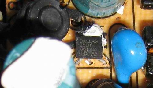
DELL AC power adapter used for my DELL Latitude D610 has an Identification wire, which is the tiny center pin in the power plug. Trying to figure it's function from the outside proves to be futile. When detached from the laptop it carries no signal, voltage, capacity or resistance. It seems like a dead wire leading no where. So it's time to figure out where this AC Adapter Identification wire is going. After cracking the case of the DELL AC power adapter, brings about a mystery electronic component. It's a transistor shaped component with 3 pins. The middle pin is connected to the AC Adapter Identification wire, the other pin to V- of the power plug. The 3rd wire is not connected.
90_1324293082.jpg

DALLAS 2501 component - connected to the 3rd wire in the AC power adapter cord
The casing of the transistor shaped mystery component has markings; "DALLAS - 2501 - 0613D2 - +571AA". Not the typical markings on a transistor. Weird!!
Pretty strange for a transistor, where all 3 pins are usually all connected.
MAXIM component, the transistor shaped device is a UniqueWare™ Add-Only Memory, known under type DS2501, DS2502, DS2505 or DS2506. The difference is the size of the memory. The DS2501 seems to be 512 byte memory. The memory is accessed using a 1 wire communication protocol known as "1-wire".
At least there is DALLAS as the manufacturer ID. This is synonym for MAXIM semiconductor.
I was able to identify the power adapter I.D. circuit in the dead power adapter. In my case it was three components on a 3/8" x 5/8" 'perf' board. (one 330 Ohm resistor, one diode looking device across the single line memory I/O port (probably surge suppression) and the single line memory device in a plastic transistor case, with only two wires connected to anything. I removed that circuit assembly from the dead adapter, and moved it from between the third wire and the minus power supply reference in the old adapter to the place in the d.c. cable where I spliced 2 wire cable into the 3-wire plug-tail from the old Dell cable, (on the adapter side of the ferrite RFI suppressor).
Without this adapter I.D. circuit, the two-wire adapter would power and run the laptop fine, but the error message indicated there was trouble with the adapter. After the I.D. circuit was added to the cable, the error message concerning the power adapter cleared and the battery charges.
So the DS2501 in the DELL AC Power Adapter contains the identification info of the power adapter. The DELL laptop reads the identification info during startup of when it's connected while started. Power for the memory device comes from the laptop which is the same AC Adapter Identification wire, indicated as a "parasite power circuit".
A new DS2501 can be soldered and programmed, with a "1-wire" programming kit and a PC with an ole RS232 jack. This is described in the Dallas Semiconductor application note 177. For electronics enthusiasts that's just a bit of fun with a soldering iron and a few low cost components.
When the programming kit is ready, next is to read the identification data from a working DELL AC Power adapter and clone it into a new DS2501 chip, already soldered into the DELL AC Power adapter.
 
Last edited:
It was a good effort and full of electronics fun. It is very nicely shred. It is exactly same as the SHARP, SONY and Pioneer did with their chip markings. I had the equivalent numbers list when I was involved in repairing TVs and audio equipment. The general ICs were available in the market at a very reasonable price where as the same under Sony or other manufacturers name was very high prices. This is indeed just a commercial tactics.
 
This is caused by Dell trying to stop people from using third party chargers. If the charger found not working properly, the problem lies not in the laptop nor the power brick itself, but the cord that runs from the charger to the laptop, due to the infamous "exploding battery" incidents companies started to use a 3-wire conductor, Ground, V+ and a data signal, this last one tells the laptop the electrical specs of the charger and if its a OEM one, if it is it charges, if not it disables charging the battery. so the problem is that the manufacturers makes this data signal cable hair thin and it usually breaks after some time, so the laptop doesn't get the charger info and disables the charging circuits,,,, but the charger itself is good. To solve the problem what i do is to open the charger (it is glued hard, and have to literally break it apart), and replace the cable with a thicker 3 or 4 wire one or cut the damaged length of wire if break found near one end, but you also have to adapt the plug from the original cable. 3rd party charger usually only have the ground and V+ conductors and no data signal one so the laptop will never charge.
DELL AC power adapter used for my DELL Latitude D610 has an Identification wire, which is the tiny center pin in the power plug. Trying to figure it's function from the outside proves to be futile. When detached from the laptop it carries no signal, voltage, capacity or resistance. It seems like a dead wire leading no where. So it's time to figure out where this AC Adapter Identification wire is going. After cracking the case of the DELL AC power adapter, brings about a mystery electronic component. It's a transistor shaped component with 3 pins. The middle pin is connected to the AC Adapter Identification wire, the other pin to V- of the power plug. The 3rd wire is not connected.
90_1324293082.jpg

DALLAS 2501 component - connected to the 3rd wire in the AC power adapter cord
The casing of the transistor shaped mystery component has markings; "DALLAS - 2501 - 0613D2 - +571AA". Not the typical markings on a transistor. Weird!!
Pretty strange for a transistor, where all 3 pins are usually all connected.
MAXIM component, the transistor shaped device is a UniqueWare™ Add-Only Memory, known under type DS2501, DS2502, DS2505 or DS2506. The difference is the size of the memory. The DS2501 seems to be 512 byte memory. The memory is accessed using a 1 wire communication protocol known as "1-wire".
At least there is DALLAS as the manufacturer ID. This is synonym for MAXIM semiconductor.
I was able to identify the power adapter I.D. circuit in the dead power adapter. In my case it was three components on a 3/8" x 5/8" 'perf' board. (one 330 Ohm resistor, one diode looking device across the single line memory I/O port (probably surge suppression) and the single line memory device in a plastic transistor case, with only two wires connected to anything. I removed that circuit assembly from the dead adapter, and moved it from between the third wire and the minus power supply reference in the old adapter to the place in the d.c. cable where I spliced 2 wire cable into the 3-wire plug-tail from the old Dell cable, (on the adapter side of the ferrite RFI suppressor).
Without this adapter I.D. circuit, the two-wire adapter would power and run the laptop fine, but the error message indicated there was trouble with the adapter. After the I.D. circuit was added to the cable, the error message concerning the power adapter cleared and the battery charges.
So the DS2501 in the DELL AC Power Adapter contains the identification info of the power adapter. The DELL laptop reads the identification info during startup of when it's connected while started. Power for the memory device comes from the laptop which is the same AC Adapter Identification wire, indicated as a "parasite power circuit".
A new DS2501 can be soldered and programmed, with a "1-wire" programming kit and a PC with an ole RS232 jack. This is described in the Dallas Semiconductor application note 177. For electronics enthusiasts that's just a bit of fun with a soldering iron and a few low cost components.
When the programming kit is ready, next is to read the identification data from a working DELL AC Power adapter and clone it into a new DS2501 chip, already soldered into the DELL AC Power adapter.


Thank you very much Alterlinks. it so nice of you to share such valuable knowledge. i am really very thankful to you.

You write here about the programming of the IC DS2501 with a "1 wire programmer kit"; is all that (IC and Programming kit) is available in the local market easily? how can i read the data from Adoptor? is there any software available on net?

can i use the same IC from the discarded Dell Adopters into my power supply and try to charge the battery of my laptop. i have Dell Inspiron 9300 in the office and my colleges have others; some have dell and hp and tosheeba etc?
 

Have a look.
**broken link removed**
Using an 8 pin microchip 10f220, I wrote the following code. It's the .HEX
:020000040000FA
:0800080005281F28A300A40035
:100010000830A2002508A306A30C2508A300031C92
:1000200013281830A306A30C2308A5002408A30056
:100030000310A30C2308A400A20B0A280800A501A2
:10004000F0300620103006200000003006200000AE
:084000000100020003000400AE
:02400E00F93F78
:00000001FF

The code aint pretty, but it works.

This sends a fake 90W signal to the mobo to make it think a dell adapter is connected. I needed it because I'm off grid and I only have 24VDC. I step this down t 18V and use the PIC to fool the mobo. Been good for 9 months now.

You'll need an old plug to connect to the laptop and you'll need to identify +, - and signal (centre) pin.
Connect 18V into the laptop. The centre pin of the goes to pin 3 of the PIC.
Put a ge diode anode on pin 3, cathode k on pin 2.
Put 0v on pin 7. 330n cap pin 2 to pin 7. You get about 2.5V on pin 2, which is just enough to power the PIC. The PIC waits about 200ms and then sends the message when requested by the mobo. There is so little current sent by the mobo that you can barely light a LED, so only use a DVM and dont connect anything else!

I've tested it on 2 d610 and 1 d600. Flawless!

You'll need a good grasp of electronics to make sense of this, not to mention programming PICs. I'm not selling these and dont intend to.

Usual disclaimers apply.

1-Wire - Wikipedia, the free encyclopedia
 

Attachments

  • app177.pdf
    187.2 KB · Views: 250
  • DS2501–UNW DS2502–UNW.pdf
    19.3 KB · Views: 190
  • Application Note 99 UniqueWareTM Project Setup Manual.pdf
    82.5 KB · Views: 169
  • eprom103.zip
    37.3 KB · Views: 163
Last edited:
  • Like
Reactions: yura717

    yura717

    Points: 2
    Helpful Answer Positive Rating
Status
Not open for further replies.

Part and Inventory Search

Welcome to EDABoard.com

Sponsor

Back
Top