Continue to Site

Welcome to EDAboard.com

Welcome to our site! EDAboard.com is an international Electronics Discussion Forum focused on EDA software, circuits, schematics, books, theory, papers, asic, pld, 8051, DSP, Network, RF, Analog Design, PCB, Service Manuals... and a whole lot more! To participate you need to register. Registration is free. Click here to register now.

Service manual for Sony KLV-L32M1 TV wanted?

Status
Not open for further replies.

Mattylad

Advanced Member level 3
Joined
Sep 7, 2009
Messages
950
Helped
231
Reputation
464
Reaction score
225
Trophy points
1,323
Location
Lancashire UK.
Activity points
7,262
Repair advice for Sony KLV-L32M1 TV wanted?

Hello,can anyone please advise on how to repair the above TV?

It turns on, there is a poor picture, no backlight.
I have found the service manual.

I have repaired CRT monitors & TV's before but not LCD ones.
 
Last edited:

I think I may have narrowed this down to the 10.5v rail not working.
I have not taken D653 out to test it yet, I cant quite get to the AC side but the unreg 30v is working off the same transformer.

However I am unsure if the 10.5v would be responsible for the backlight?
Other items, menu etc are visible on the screen but very dim, there is also slight flickering.
 

Attachments

  • SONY_TV_KLV-L32M1-AEP.pdf
    10.2 MB · Views: 517
Last edited:
  • Like
Reactions: mihum

    mihum

    Points: 2
    Helpful Answer Positive Rating
10.5v is there too.

Has anyone any suggestions where I may look for repairing this TV?
 

Can anyone help or advise where else I can find help to fix this TV?

Thank you.
 

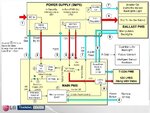
Try to measure the control signals between the microprocessor and the LCD inverter. These signals have various functions related to the brightness of the lamps.
 

Attachments

  • lcd1.JPG
    lcd1.JPG
    73.9 KB · Views: 420
  • lcd2.JPG
    lcd2.JPG
    52.6 KB · Views: 284
  • lcd 3.JPG
    lcd 3.JPG
    69 KB · Views: 290
  • 2010-08-31_052159_LCD.jpg
    2010-08-31_052159_LCD.jpg
    249.5 KB · Views: 693
Thank you for the suggestion, I will revisit this TV in a few days when I have time and identify the voltages on the connectors.
 

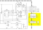
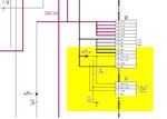
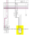
I have finally measured the voltages, thers is only 1 connector going to the backlight board from the others, it comes from the PSU as:
CN652
1-5 = 16.33v
11 = 3.6v
12 = 3.23v
13 = 2.76v

The backlight on/off control from the processor board as CN653 is:
3 = 2.76v
2 = 3.26v
1 = 3.6v

These are the voltages identified on the bottom of BL 1/5 3-13 at CN1004 (almost) the PANEL DET is almost 1v less but I am not sure if this matters?

It is looking to me looking this may the inverter board itself, I need to hurry with diagnosing this today as there is a spare on Ebay I can get.

---------- Post added at 14:30 ---------- Previous post was at 13:56 ----------

I have also looked at the inverter board, however there never seems to be schematics for these in Sony manuals (I suspect because of the high voltages).

None of the IC's are hot, there seems to be 55-75 volts on the transfomers.

This makes me worry about the panel det line being low - why & does it matter?
 

The LCD screen displays is dark/ dim because there is no backlight. There are two parts responsible for lighting the display:
CCFL (Cold Cathode Florescent Lamp) which is the back light and the Inverter board which provides high voltage to the CCFL.
In this case either of the parts can be faulty.
For the CCFL lamps to check if they are working or not you need a CCFL Lamp Tester , or you may use a special method called as “Bypass Inverter Protection”. This method will let you know if either the CCFL lamps or the inverter board problem that had caused the LCD TV to shut down, and require to identify partial schematics of the inverter board, the inverter ICs and their datasheets, for bypass timing capacitor to set striking time and shutdown delay time. Well, now considering the actual inverter, that’s a difficult task to do. :sad:
In my opinion that’s a 50-50% chance if you buy the inverter board or to replace the CCFL lamps. Replacing the CCFL backlight lamp on LCD screen is a lot more difficult then replacing an inverter. This is a very delicate operation. CCFL is an extremely small fluorescent lamp and you must handle them with extra caution.
 
OK thank you, I take it that the PANEL DET line being low is OK then.

What sort of voltage should I expect out of the inverter outputs?
I have a HV probe somewhere I can dig out.

Thank you for your help.

---------- Post added at 15:26 ---------- Previous post was at 15:17 ----------

I have found LCD TV Repair Tips - How To Bypass LCD TV Inverter Board Shutdown Backlight System and will try this quickly to see if it is the inverter or not.

---------- Post added at 16:11 ---------- Previous post was at 15:26 ----------

This inverter board appears to have an OZ976TN instead of a OZ9938 IC and I cannot find a datasheet to show me the pin.

The TV was given to me so am hesitant to spend money until I can identify the fault.

Although I think I may as well just take a punt on the inverter.

Although.. what if I power it up with one ccfl connector at a time not connected?
If its a tube wouldn't this show that a tube is down or is the detection circuit likely to have a voltage on it even without the tube?
 

I have tried unplugging individual inverter connectors and powering up, makes no difference.

Am making enquiries about a replacement board, if I can get that cheaply enough its worth a punt.
 

Look what I have found about OZ976. Local inverters controlled by OZ972 circuits.
 

Attachments

  • lc370w01_oz976tn_oz972gn_inverter.pdf
    992.1 KB · Views: 207
CCFL lamps looks bad...Try to test lamps with CCFL tester
File uploaded
 

Attachments

  • CCFL TESTER.pdf
    1.1 MB · Views: 2,535
Test your Lamps first with Tester circuit,Is there glow or not,If lamps works good you need to test your LCD.TV CCFL output circuit
Also this will helps you.
 

Attachments

  • LCD_TV_Inverter_Output_Test.pdf
    173 KB · Views: 230
I have the new inverter board.
With the old one in situ, the sound and display work - I can see a picture in the background but it is very dim.
Everything is OK except no backlight IMO.

However, when I fit the new inverter board I get nothing, turn on and the pwr led is green for a few secs then keeps flashing red.
No picture, no sound nada.

Now Is this likely that the board is indicating to the processor that there is a fault before it dies or is it likely that the board itself is faulty?

Also, what would the effect of having it turned on while the tubes themselves are disconnected?
Can I try 1 tube at a time to see if they work? (or do they need connecting in pairs etc?)
 

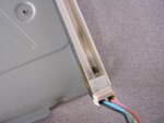
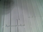
Its Looks to me as a Faulty or Bad CCFL Tubes,See the pictures
 

Attachments

  • brunt ccfl.jpg
    brunt ccfl.jpg
    28.6 KB · Views: 217
  • DSC_0000101.jpg
    DSC_0000101.jpg
    33.1 KB · Views: 183
Is this likely to be all of them?

Will all the tubes have gone or should I be able to disconnect all and plug in individual tubes to see if it works?

Does the board shut down if all tubes are not connected?

Also you gave the circuit for a CCFL tester, do you have any details on the transformer in it?
I cannot see anything about this, otherwise would build one.
(Testers are on ebay but will take 2 weeks to arrive and cost more lol)
 
Last edited:

Re: Service manual for Sony KLV-L32M1 TV wanted

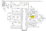
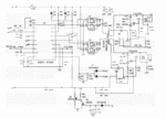
The OZ972s drive the CCFLs after receiving an Enable signal. During the Soft Start Time, all OZ972 in open lamp condition attempts to ignite the CCFLs. In this soft-start period, line TALK is pulled low and a ‘’striking frequency’’ is provided by the controller OZ976. As each OZ972 circuit may take a different time to regulate the CCFL current (due to lamp and component tolerances) there’s a capacitor connected to the CTIMR pin to compensate the maximum striking time. When the OVP pin reaches a 2.22V threshold, the CTIMR capacitor starts to charge. If the CTIMR voltage reaches approximately 3V and no current is sensed, the OZ972 protection block shuts down the circuit.
Timing calculation: T[second] = C[uF]
The shut down behavior does not affect the operation of the other OZ972’s and lamps, so the remaining OZ972’s successfully regulate their lamp current and TALK signal is released (level high) and informs the OZ976 to switch to a normal operating frequency. In the event of some OZ972 in shut down condition, after a period of 20us those circuits pulls TALK line to low level and informs the OZ976 controller of an abnormal condition. The OZ976 response is related also to the IND pin setting to decide whether to disable all the inverters or not.
When IND pin feature is set level high, all OZ972s work individually. In this situation, when a lamp is damaged or open, the corresponding OZ972 will shut down and pull TALK low, indicating to the OZ976 that an abnormal situation exists but OZ976 will ignore the TALK level low and maintain system operation.
When IND is set level low, all OZ972s work as a group. Once the OZ976 detects a TALK falling edge, the OZ976 pulls ENA_Pp signal low to disable all the inverters.
The idea is to set IND pin on OZ976 to high level, power circuit and check the result on OZ972 circuits. Any broken lamps will block the correspondent controller .
Later you may decide to use “Bypass Inverter Protection” forcing the ‘’abnormal’’ OZ972 circuit in order to determine broken lamps.
 

Attachments

  • mod OZ976_v1a.GIF
    mod OZ976_v1a.GIF
    48.4 KB · Views: 256
  • OZ972 diagram.GIF
    OZ972 diagram.GIF
    87.8 KB · Views: 248
Last edited:
My problem now is identifying the tubes I would need, apart from which ones - the size etc and this would mean taking it completely to pieces.
Not too keen on doing that and leaving it on the kitchen table while I find replacements.

I cannot test them as I do not have a tester and cannot build one without knowing the transformer details.
I think its time to pass it on unless I can get more info on the tubes.
 

Status
Not open for further replies.

Part and Inventory Search

Welcome to EDABoard.com

Sponsor

Back
Top