Continue to Site

Welcome to EDAboard.com

Welcome to our site! EDAboard.com is an international Electronics Discussion Forum focused on EDA software, circuits, schematics, books, theory, papers, asic, pld, 8051, DSP, Network, RF, Analog Design, PCB, Service Manuals... and a whole lot more! To participate you need to register. Registration is free. Click here to register now.

Need 24volt battery charger with 50Amps current

Status
Not open for further replies.

grittinjames

Advanced Member level 1
Joined
Jun 1, 2006
Messages
479
Helped
44
Reputation
90
Reaction score
32
Trophy points
1,308
Location
bangalore india
Activity points
3,985
Hi all,
Please help me to find a good circuit for SMPS battery charger.
24V battery,
Max Charging current-50Amps

Thanks
Grittin James
 

What type of battery, what is your charging source?
 

you can use a 24v/50A power supply(with current limit) for LEAD ACID type.
adjust it on 28.8V and connect it to your battery.
when batt voltage is lower than 28.8 it will charge with 50A and afterwards it goes in the constant voltage region.
a battery charger is just a current limited voltage source. (14.4v for 12v battery and 28.8 for 24v at 20c to 30c ambient temperature)
 
Last edited:

Please post some link to complete project.
I want to charge from 180Vac to 260Vac
 

This project was published by the german magazine ELV in late 90's .
Its a switchmode labsupply regulating from 0 to 30 Volt and upto 20 Ampere with voltage and current regulation .
Being a SG3525 fullbridge it can continues deliver 600 Watts at an efficiency upto 90 % .
Only minus is that the article is in German ,but the project is to good not to put it here just for the language .
Being a labsupply its complete with meters based on the icl7106 .
Little note about safety .
For testing they advise to use a 1000 Watt separation transformer .
Always be carefull when working with mainsvoltage ,
It can be a good start for making and modifying according to your requirements.
 

Attachments

  • 030v-020a_power.pdf
    1.2 MB · Views: 950
Hi,
It looks good, But too old, Now days no one uses SG3525.
Please let me know if some one have any modern circuit
Thanks
Grittin
 

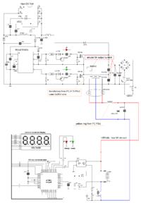
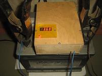
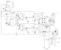
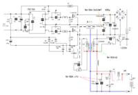
May be this scheme is useful. It is for 12V 55Ah car battery, but remake for 24V 50A not so complicated.
 
Last edited:

So which parts would you replace, seems like a big jump to me. I want it to charge a solar bank on cloudy days. I don't see how the voltage is determinded. I don't see any zener diodes. Does this shut off at full charge. I don't see that ether. the two diodes coming out of the transformer that are circled look like zeners but that dosen't make sense to me as it should be high speed high current. I can't cross the number that is listed. I would like some help. Thank You. Dan
 

no one uses the sg3525??????? im dumb, i do !!!! im so new to power electronics and already outdated....

what is used then now cheaply, reliable and easy to deploy???? Cause less then 4 mm qfn power ic's are not. and the electromagnetics rules and laws are surely the same...
 

Hi, all.

I don't see how the voltage is determinded.
voltage determninded by battery, in general, because power of PSU is limited by the capacity of half-bridge capacitors;
I don't see any zener diodes.
You may see two as minimum );
Does this shut off at full charge.
yes, and mcu also provides protection from shorting of output wires and reversing batteries;
the two diodes coming out of the transformer
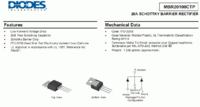
it is MBR20100, 2x 10A 100V schottky diode (taken from old PC PSU), of course possible use something another, such as SR30100;
For charging 24V batteries possible use two such devices because 24V battery usually consists of two or more 12V units. However come to increase half-bridge capacitors before 68nF and capacitor in 310V chain before 330uF. Also be necessary to do more powerful transformer and output chains.
Or possible do one powerful block for charging whole 24V battery.
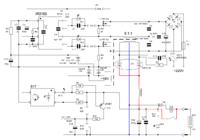
Like this -
And, of course, nothing do not disturb to do same on any pwm chip like tl494, sg3525, uc3825, etc., except that several greater difficulties.
 
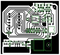
ok, so pcb picture for this
and better if R2 must be 100 Ohm, not 50.
And, also - for this scheme it is need only ir2153. Not irs2153, ir2153D, irs2153DS. But with Viper (or any other aux ps) possible to use any version of ir2153.
 
Last edited:

Schematic for device without self regulation and with manual on and off.

Suitable for transformer calculation -
And also possible think on that to use cheap chinese welding device as powerful charger.
But more correctly to charge such batteries with pulse current rather then pure dc. This may be provided with using mcu or 555 timer as control scheme of charger device.
 
Last edited:
I see only one zener, is that correct.
yes, but possible add else pair if anybody desire. )
What is 1.5KE100ca.
it is supressors for protect rectifier diodes from surge spikes.

What is REL 1
For absence of mcu this relay protects scheme from reversed battery.
12v 5a. Is that an oversight.
no, changes required for obtaining 50А is specified in accordance with colour line. For сharging 24V battery it is necessary to take two such device or one more powerful with another scheme.
How can I print this.
what progs you want use to do this? Usually apply "fit to page" function is enough, in win"Paint" for instance.

Else possible make not bad charger based on thansformers taken from old UPS which possible gain for price not more 4 USD.
 

Status
Not open for further replies.

Similar threads

Part and Inventory Search

Welcome to EDABoard.com

Sponsor

Back
Top