Continue to Site

Welcome to EDAboard.com

Welcome to our site! EDAboard.com is an international Electronics Discussion Forum focused on EDA software, circuits, schematics, books, theory, papers, asic, pld, 8051, DSP, Network, RF, Analog Design, PCB, Service Manuals... and a whole lot more! To participate you need to register. Registration is free. Click here to register now.

230V AC dimmer, mains isolated.

Status
Not open for further replies.

DanyR

Member level 3
Member level 3
Joined
Aug 23, 2015
Messages
67
Helped
6
Reputation
12
Reaction score
6
Trophy points
8
Location
Nieuwpoort, Belgium
Activity points
677
230V AC dimmer, mains isolated, using P12F629

This is a very simple dimmer with a triac output (phase control). It uses timer0 to do the timing.

The code is written in mikroPascal.

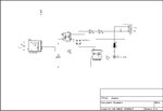
The control part (here a P12F629) is competely isolated from the 230V mains supply:
- the zero crossing detector contains an optocoupler (4N25 or similar),
- the drive of the triac also contains an opto coupler (MOC3025 or similar). Be aware: the latter optocoupler should NOT have a zero cross detection!

The 5V power supply is not drawn in the schematic.

The ignition angle can be set in the example by setting the value of Tmr0 at the end of the zero crossing detection. The example uses only these 3 values, see the comments below:

Case Step of
0: Tmr0 := 0; // never ignite triac (delay > 10 ms)
1: Tmr0 := 140; // low value = long delay = late ignition = low power
2: Tmr0 := 175; // average power
3: Tmr0 := 250; // high value = short delay = high power
end;

Schematic:
Dimmer.jpg

Code:
 

Attachments

  • Dimmer.zip
    69.6 KB · Views: 202
Last edited by a moderator:

could you post the correct circuit? isn't isolated, as pin 2 from the 220-lamp connector (which goes to the triac) is connected to VSS and thus to the 5V power supply...
 

As far as the load is resistive, this type of dimmer is ok. What is your opinion about driving inductive load like transformer?
 

could you post the correct circuit? isn't isolated, as pin 2 from the 220-lamp connector (which goes to the triac) is connected to VSS and thus to the 5V power supply...
You are so right, the circuit diagram was wrong. Thanks for the reply.

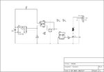
This is the corrected diagram:
Dimmer.jpg.

The corrected zipfile (including the code):

So sorry for the inconvenience! :shock:
 

Attachments

  • Dimmer.zip
    69 KB · Views: 180

As far as the load is resistive, this type of dimmer is ok. What is your opinion about driving inductive load like transformer?
Hi,
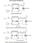
Here is some application information stated in the datasheet of the MOC3020:

Capture12-10-2015-20.57.22.jpg

Additionally a snubber circuit across the triac may be needed, e.g. 47 ohms in series with 0.01uF
 

the zero crossing detector contains an optocoupler (4N25 or similar),
The opto 4N25 has not a good gain, so that for low angles the circuit will not be able to detect precisely the phase where zero cross happens.
 

The opto 4N25 has not a good gain, so that for low angles the circuit will not be able to detect precisely the phase where zero cross happens.
Hi André, Thanks.
I must admit I did my actual project with a TIL111 optocoupler, which has a minimum CTR of 50%, while the 4N25 has a minimum CTR of 20%. The reason for the difference is that I doubt if the TIL111 is easily obtainable, and I also have no LTSpice model for it...

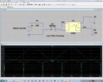
Nevertheless, an LTSpice simulation shows it should work with the 4N25 (I assume they have the CTR set tp 20% in the 4N25 spice model...):

Zero_Crossing_4N25.jpg
 

The opto 4N25 has not a good gain, so that for low angles the circuit will not be able to detect precisely the phase where zero cross happens.
Hi André,
I see that the 4n25 model in LTSpice has a CTR of 73% (measured in a simulation), so that is probably the reason why the zero crossing detector works well in an LTSpice simulation...

I did the same simulation with a CTR of 20%, and the zero crossing pulses are somewhat wider then, which means the start of the zero crossing is detected too soon, and the end of it detected is too late.
This can result in not be able to trigger the triac at a very early time after the zero crossing, resulting is a slightly less max power for the load.
 

Status
Not open for further replies.

Part and Inventory Search

Welcome to EDABoard.com

Sponsor

Back
Top