Continue to Site

Welcome to EDAboard.com

Welcome to our site! EDAboard.com is an international Electronics Discussion Forum focused on EDA software, circuits, schematics, books, theory, papers, asic, pld, 8051, DSP, Network, RF, Analog Design, PCB, Service Manuals... and a whole lot more! To participate you need to register. Registration is free. Click here to register now.

How to test a Sidac ? thanks

Status
Not open for further replies.
How to test a Sidac ?

General Description
The Sidac is a silicon bilateral voltage triggered switch with
greater power-handling capabilities than standard diacs. Upon
application of a voltage exceeding the Sidac breakover voltage
point, the Sidac switches on through a negative resistance region
to a low on-state voltage. Conduction will continue until the current
is interrupted or drops below the minimum holding current of
the device.
Normally Vbo range 95 - 330 Volts

Example datasheet
http://www.play.com.br/datasheet/SIDAC.pdf

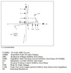
Sidac V/I Characteristics
SIDAC_V-I_Characteristics_text_.jpg

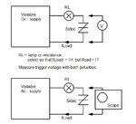
Test circuit
SIDAC_Test_Circuit.jpg
 
General Description
The Sidac is a silicon bilateral voltage triggered switch with
greater power-handling capabilities than standard diacs. Upon
application of a voltage exceeding the Sidac breakover voltage
point, the Sidac switches on through a negative resistance region
to a low on-state voltage. Conduction will continue until the current
is interrupted or drops below the minimum holding current of
the device.
Normally Vbo range 95 - 330 Volts

Example datasheet
http://www.play.com.br/datasheet/SIDAC.pdf

Sidac V/I Characteristics
View attachment 62721

Test circuit
View attachment 62720

Ample amount of Thanks to you

By IH, IT & Iload , did you mean that :

I H ==> Dynamic Holding Current 50/60 Hz sine wave

IT (RSM) ==> On-State RMS Current

& Iload ==> Vload / RL , where Vload is ------ ? & RL is that Iload > IH & Iload < IT(RMS)

Am i right ?

Every Sidac has to be tested with both Variable DC Supply & Variable AC Supply one by one ???

What should be the values (Range) of AC & DC Supplies ?

What do you mean by that " Measure Trigger voltage with both polarities " ? Do you mean by that connect voltmeter (in DC V scale) when Red Probe on RL side & Common Probe on Iload side & then reverse the procedure like that, connect Common (Black) probe on RL side & Red Probe on Iload side ??

Am i comprehending this right ?

thanks
 
I H ==> Dynamic Holding Current 50/60 Hz sine wave
IT (RSM) ==> On-State RMS Current
& Iload ==> Vload / RL , where Vload is ------ ? & RL is that Iload > IH & Iload < IT(RMS)
Am i right ?

Yes

Every Sidac has to be tested with both Variable DC Supply & Variable AC Supply one by one ???

No, they represent alternative methods for testing. ( test with DC or with AC )

What should be the values (Range) of AC & DC Supplies ?

Look V/I - characteristics.

Test voltage must be higher than VBO ( Breakover voltage) so that SIDAC turns conductive and
voltage across component drops to VT ( On state voltage)
Same test must be done for both polarities +V and -V.

If you use AC-voltage and scope both voltage drops can observed simultaneous.

If Dc-voltage is used , measure first another half of characteristic
- find point VBO ( for example +V) = value where voltage drops to VT
- slowly increse voltage until you find that point
- then change polarity in supply and meter for measuring another half. (-V)

What do you mean by that " Measure Trigger voltage with both polarities " ? Do you mean by that connect voltmeter (in DC V scale) when Red Probe on RL side & Common Probe on Iload side & then reverse the procedure like that, connect Common (Black) probe on RL side & Red Probe on Iload side ??

Look above
 
Yes


No, they represent alternative methods for testing. ( test with DC or with AC )


Look V/I - characteristics.

Test voltage must be higher than VBO ( Breakover voltage) so that SIDAC turns conductive and
voltage across component drops to VT ( On state voltage)
Same test must be done for both polarities +V and -V.

If you use AC-voltage and scope both voltage drops can observed simultaneous.

If Dc-voltage is used , measure first another half of characteristic
- find point VBO ( for example +V) = value where voltage drops to VT
- slowly increse voltage until you find that point
- then change polarity in supply and meter for measuring another half. (-V)


Look above


thanks what about Vload ?? How to evaluate its value ?
 
thanks what about Vload ?? How to evaluate its value ?

You can imagine SIDAC as two parallel thyristors in opposite directions , thyristor trigger at voltage VBO.

We can calculate dynamic resistance at VBO
Rdyn sidac = VBO / IBO

Look datasheet SIDAC MKP1V240
https://www.onsemi.com/pub_link/Collateral/MKP1V120-D.PDF

in page 2. Table : ON CHARACTERISTICS

VBO = 220V
IBO = 35µA
so Rdyn at point VBO is 6.3 Mohm

at this point sidac turns conductive
and voltage across sidac drops down to 1.3V

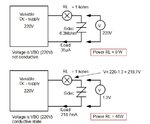
so we have two situations to handle

SIDAC_Test_RL_Pow_.jpg
 
You can imagine SIDAC as two parallel thyristors in opposite directions , thyristor trigger at voltage VBO.

We can calculate dynamic resistance at VBO
Rdyn sidac = VBO / IBO

Look datasheet SIDAC MKP1V240
https://www.onsemi.com/pub_link/Collateral/MKP1V120-D.PDF

in page 2. Table : ON CHARACTERISTICS

VBO = 220V
IBO = 35µA
so Rdyn at point VBO is 6.3 Mohm

at this point sidac turns conductive
and voltage across sidac drops down to 1.3V

so we have two situations to handle

View attachment 62773

thanks for your phenomenal replies

would the test for AC Variable supply be the same as for DC Variable Supply (as you mentioned in the work out example) ?

What should be the output in both case AC Variable Supply & for DC Variable Supply ?

Does the value of DC Variable Supply keep constant to 220 V DC or vary down from 0 to 220 V DC ?

thanks, i would give you points for sure don't worry
 
Here is one example more...............
SIDAC_Test_Circuit_P2osc.jpg

With DC-supply and meter
same as above but...
-increase DC voltage slowly so that you can find value VBO and VT
ie max. value for voltage across the Sidac just before it drops down to VT
-do this with both polarity
 
Last edited:
Here is one example more...............
View attachment 62812

With DC-supply and meter
same as above but...
-increase DC voltage slowly so that you can find value VBO and VT
ie max. value for voltage across the Sidac just before it drops down to VT
-do this with both polarity

What do you mean by that " increase DC voltage slowly so that you can find value VBO and VT
ie max. value for voltage across the Sidac just before it drops down to VT " ?

Do you mean measure the voltage with oscilloscope ?
And, increase the DC voltage from where to where ??
 
Look picture Sidac V/I Characteristics
in post

https://www.edaboard.com/threads/227947/#post972018

In manual test with DC you move along horizontal axis (voltage)
by increasing supply voltage higher than VBO.
In point VBO voltage across sidac drops to VT.
If your supply voltage goes higher after that
only power dissipation in RL increase.
 
You can imagine SIDAC as two parallel thyristors in opposite directions , thyristor trigger at voltage VBO.

We can calculate dynamic resistance at VBO
Rdyn sidac = VBO / IBO

Look datasheet SIDAC MKP1V240
https://www.onsemi.com/pub_link/Collateral/MKP1V120-D.PDF

in page 2. Table : ON CHARACTERISTICS

VBO = 220V
IBO = 35µA
so Rdyn at point VBO is 6.3 Mohm

at this point sidac turns conductive
and voltage across sidac drops down to 1.3V

so we have two situations to handle

View attachment 62773

How did you evaluate the values of RL = 0W & RL = 48 W in both states i.e. conductive & non conductive ?
What exactly RL is ? Should i take a lamp or a resistor ?

As in this pic you're providing DC variable supply 220 V in both states (conductive & non conductive) then, how can you say that the above one is non-conducting state & the below one is conducting state ?

did you mean that below 220 V the sidac would be in non-conducting state & as the supplied voltage reach to 220 V the Sidac turn to its conducting state, Am i right ?

https://obrazki.elektroda.pl/31_1321453546.jpg
https://obrazki.elektroda.pl/100_1321453546.jpg

what do you mean by both polarities + V & - V ?

thanks
 

Status
Not open for further replies.

Similar threads

Part and Inventory Search

Welcome to EDABoard.com

Sponsor

Back
Top