Continue to Site

Welcome to EDAboard.com

Welcome to our site! EDAboard.com is an international Electronics Discussion Forum focused on EDA software, circuits, schematics, books, theory, papers, asic, pld, 8051, DSP, Network, RF, Analog Design, PCB, Service Manuals... and a whole lot more! To participate you need to register. Registration is free. Click here to register now.

SG3525 2500Watt Sine wave inverter, purpose of using VR1

Status
Not open for further replies.

kg300

Member level 3
Member level 3
Joined
Sep 21, 2007
Messages
67
Helped
62
Reputation
124
Reaction score
67
Trophy points
1,308
Location
RY Khan - PAK
Activity points
1,852
what's the purpose of using VR1 and VR2 in this circuit?
 

Attachments

  • 2500w.PDF
    38.7 KB · Views: 1,612

VR1 is for feedback to adjust the output voltage and to maintain that constant output voltage. VR2 is probably for adjusting for overload protection.

Hope this helps.
Tahmid.
 
Hello Kg300 can you post the complete schematics of the inverter i am interested
 

hi all,
what's the purpose of using D16 diode in this circuit?
 

what's the purpose of using VR1 and VR2 in this circuit?
VR1 is provided for adjusting pwm output dc voltage feeding to the h-bridge fets and VR2 is for adjusting the output voltage for the load,
I think it'll be helpful .
 

Hi Tahmid,

In that inverter circuit, why they have converted the battery DC Voltage to AC and again rectifyng making to High Voltage DC?? Why cant they make the battery DC voltage directly to required AC output through that transformer?? Why they need that many conversion??? Kindly suggest me on this.
 

It is an SMPS design. It is a 2-stage converter. Instead of standard bulky iron core transformers, ferrite core transformers are used, that work at high frequencies. They are much smaller than the regular bulky iron core transformers. Since they only work at high frequencies, the high frequency AC is converted to DC and a bridge converter is used to convert that DC to 50Hz (or 60Hz) for AC output.

This type of inverter can greatly reduce cost and size compared to bulky iron core transformer based inverters.

Hope this helps.
Tahmid.
 
Tahmid,

Am asking about conversion. Is it necessary to have 2 stage conversion??? Or can we do that 12V DC to 230VAC directly from transformer(By pulsating the DC and giving to transformer primary).

---------- Post added at 14:14 ---------- Previous post was at 14:13 ----------

Step Up transformer...Stepping up the 12V to 230V
 

You can do that, but not with a ferrite core. The ferrite core can only be used at high frequencies like 50kHz or higher. So, if you pulsate it, at the output you can have 220VAC but at 50kHz (kiloHertz). This can not be used to drive most loads. So, it must be converted to 50Hz and hence the 2nd stage.

If you use an iron core transformer (the bulky ones), you can do it in one step where the transformer can be used at 50Hz.

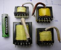
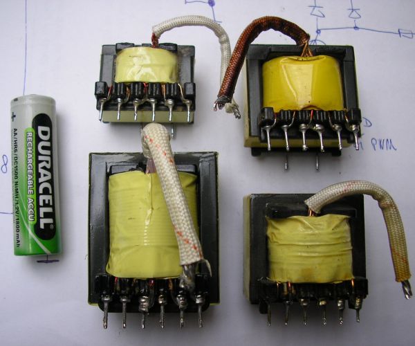
These can be used for 2-stage conversion inverters and can take quite a lot of load for the size (just look at the size compared to the battery):


22_1331826656.jpg

Source: **broken link removed**

The two bottom ones in the above diagram can be used for more than 100W (depending on circuit and frequency used, etc).

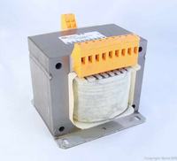
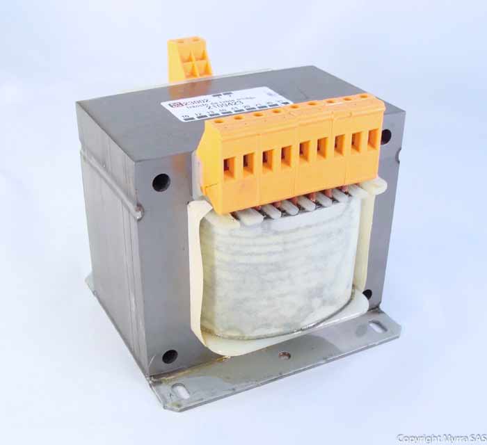
This can be used for 1 step conversion:

100_1331826813.jpg

Source: https://www.europages.com/filestore/gallery/6c/ed/6671339_d30fea91.jpg

Compare the sizes.

If you want 1 step conversion, then you can use a 50Hz transformer. If you use the ferrite transformer, you have to use it at kHz range and then convert back to 50Hz via the 2nd stage.

Hope this helps.
Tahmid.
 
Hi All, Has anybody built this Inverter...? Can you please post complete ckt diagram...
 
tahmid can share more light on how to rewire this transformer for more power like 1000w to 1500w
thanks
 

Status
Not open for further replies.

Similar threads

Part and Inventory Search

Welcome to EDABoard.com

Sponsor

Back
Top