Continue to Site

Welcome to EDAboard.com

Welcome to our site! EDAboard.com is an international Electronics Discussion Forum focused on EDA software, circuits, schematics, books, theory, papers, asic, pld, 8051, DSP, Network, RF, Analog Design, PCB, Service Manuals... and a whole lot more! To participate you need to register. Registration is free. Click here to register now.

capacitor size to remove ripple?

Status
Not open for further replies.

logmode

Newbie level 5
Newbie level 5
Joined
Aug 30, 2011
Messages
9
Helped
0
Reputation
0
Reaction score
0
Trophy points
1,281
Activity points
1,354
Hi, I want to build a power supply @ 25v a/c in and a variable 0- 20vdc, 10a max out. So that’s the plain. After the rectifier, I want to put a capacitor to smooth out the pulse. Now my question is: Does anyone know the formula to find the UF capacitance? Plus and minus information on error sizing would greatly appreciated, for since my current will be sometime low, and sometimes high (different loads), how do I use the formula for that?
Thank you
 

Some info here:
**broken link removed**
Power Supplies
Smoothing capacitor for 10% ripple, C = ( 5 × Io) /(Vs × f )
C = smoothing capacitance in farads (F)
Io = output current from the supply in amps (A)
Vs = supply voltage in volts (V), this is the peak value of the unsmoothed DC
f = frequency of the AC supply in hertz (Hz)
10% ripple, Vs=25V, Io=10A, f=50Hz > C= 0.04F= 40.000 uF (rated for 35V-50V)
 
Hi logmod,
You specified 25 volts AC input and then 0-20 volts variable supply. Can you please tell me how you will get this 0-20 volts varying. Will you be using a linear regulator or a switching regulator or some other combination? As the reply will vary on different ACTIVE components.
 
You may use a single large capacitor 22.000- 33.000uF/35-50V, or you may put two or more caps (4700-6800uF/35V) in parallel to obtain the proper value. Smaller capacity caps charge and discharge faster by their nature and placing more in parallel will divide their impedance, and you must go for lower impedance value.
 
Hi,
I am using a regulated power supply variable from 0-18 Volts and 16.0 amps (with current limit circuit) for charging the batteries from 7Ah to 120 Ah.
I used same IC (LM723) and the filtering capacitors as 10,000 µFx3 it is working perfectly fro the last 7 years without problem.
Hope it helps, any further query welcomed.
 

The following formula gives a rough approximation for a full wave rectifier.
C = 100/(wRP)
Where
. w = mains frequency in radians/second
. R = effective load resisitance
. P = Percentage ripple
The formula is reaonably accurate for P <=10%
.
Also, see Center-tap Full-wave Rectifier
 

Hello,
In link- **broken link removed** I found “For a full-wave rectifier on 50 Hz mains, f is 100 Hz”. But in the very helpful example 50 Hz was used instead of 100Hz, why? Also, I am not clear what the 5 is in -- C = ( 5 × Io) /(Vs × f )


HTML:
mister_rf
Some info here:
[I]**broken link removed**[/I]
Power Supplies
Smoothing capacitor for 10% ripple, C = ( 5 × Io) /(Vs × f )
C = smoothing capacitance in farads (F)
Io = output current from the supply in amps (A)
Vs = supply voltage in volts (V), this is the peak value of the unsmoothed DC
f = frequency of the AC supply in hertz (Hz)
10% ripple, Vs=25V, Io=10A, f=50Hz > C= 0.04F= 40.000 uF (rated for 35V-50V)
 

The full-wave rectifier passes both halves of the ac cycle to either a positive or negative output, as effectively you created 2 peaks for each cycle on the supply, so instead 50Hz we get double frequency pulses= 100Hz.
 

mister_rf is correct regarding the frequency doubling of a full wave rectifier. The formula that I gave in my earlier post takes this into account.
 

Hello,
So what did I do wrong?
W = 100 Hz = 628.31853 rads/sec
R = effective load resistance = E/I=25v/10a = 2.5 ohms
P = percentage ripple = 25v (.10) = 2.5v-(a ten percent ripple)
C = 100 / (WRP) = 100 / (628.32*2.5*2.5) = .0254647 F = 25464 UF
 
Last edited:

mister_rf
**broken link removed**
Power Supplies
Smoothing capacitor for 10% ripple, C = ( 5 × Io) /(Vs × f )
C = smoothing capacitance in farads (F)
Io = output current from the supply in amps (A)
Vs = supply voltage in volts (V), this is the peak value of the unsmoothed DC
f = frequency of the AC supply in hertz (Hz)
10% ripple, Vs=25V, Io=10A, f=50Hz > C= 0.04F= 40.000 uF (rated for 35V-50V)
In your calculations there is figure (in blue text 5) what is it, ANY CONSTANT? If yes what or where from this value came?
I could not find any thing like this. Can you explain ?
 
Logmode,
I'm assuming that your mains frequency is 50 Hz. The formula takes into account the frequency doubling of a full wave rectifier. So w = 314.2. If the actual mains frequency is 100 Hz, then the number you used for w is correct.
.
P is the percent ripple, not the ripple voltage, so you should use p = 10.
.
Remember, the formula is only an approximation.
 
Hi,
Understood it’s an approximation.
I am so sorry I would never want you to assume, Frequency is 50 Hz.

W = 314.2 then
C = 100 / (WRP) = 100 / (314.2*2.5*10) = 100 / 7855 = .0127307 F = 12730 UF.

Thank you :)


Note: I corrected my mistakes , sorry.
 
Last edited:

Hi all,

This is old, but really useful: Schade curves.
These universal curves give regulation, ripple and currents for dimensioning capacitors and diodes for several rectifier types.
Regards

Z
 

Attachments

  • Schade Curves.rar
    320.3 KB · Views: 110
  • Like
Reactions: Kral

    Kral

    Points: 2
    Helpful Answer Positive Rating
Hello,
mister _rf’s C=( 5 x Io) / ( Vs x f) was nice but not explained, and came up with 40,000 UF.

Kral’s C = 100 / ( WRP ) (Well done) came up with 12730 UF.
I found another one
C=.01(10)/2=.05 F*1000000=50000 UF
C = (TI)/V = farads
T= time between diode conductions (in seconds)
I = load current
V = is ripple voltage wanted


So let’s see- 50,000, 40,000, and 12,730. Oh dear!
 

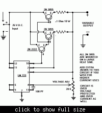
If you desire up to 10 amps at low voltage output do you realize how much heat dissipation there will be in series pass 2n3055's?

You may also have problem with high turn on surge current to charge the filter cap when turning on unit.
 

Status
Not open for further replies.

Part and Inventory Search

Welcome to EDABoard.com

Sponsor

Back
Top